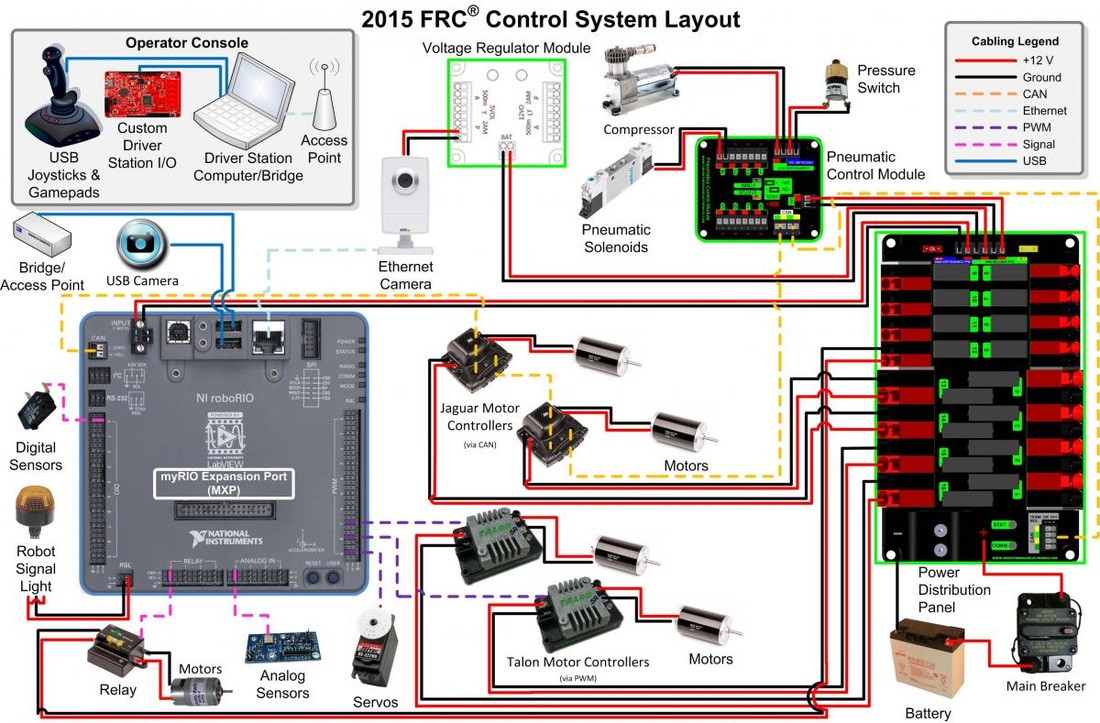
Hello, I’m a participant in the FIRST Robotics Competition (FRC) and am trying to create a system, utilizing fritzing, that any team can use to create a visual diagram of their electronics. Below is a picture of what a common wiring schematic looks like in FRC. Unfortunately I’m a mere novice with Fritzing and am having a great deal of trouble using fritzing to create custom parts and import them into fritzing. I have found some tutorials online, but they’ve mostly been unhelpful for my particular use. I was wondering if someone on here could help. Thank you!
Someone a while back asked for the robotRIO and a fritzing part for it is available here:
It looks like some of (with guesses at position which should be close enough probably all of) the the data needed to make parts is available here:
Peter
What is some data needed to create custom parts? I know where to find high quality graphics of basically all the components I need, just not how to import them into fritzing.
If you want tutorials.
The picture you posted above is not created with Fritzing. It is nothing more than a collage of pictures connected with colored lines. If all you need is a picture like the one above I would suggest using something like G.I.M.P… If you also need to create a proper schematic and/or a PCB then Fritzing is the correct tool.
Sublimeartistry I am aware that the diagram was not created on fritzing, I provided it to show what the wiring and some of the requirements I am looking to meet. My goal is to create fritzing parts for all of FRC’s control system, so that teams can lay out their specific layout.
I expect as this is a student competition, that Fritzing is the correct answer. I expect as part of the competition they have to provide documentation and Fritzing is a good solution to that. The worst part of this project (The roboRio module with 140 or so connections) I already did (although not that well I see when I ran the check script on it this morning ![]() ). This is basically what I usually use Fritzing for, documenting the connections between a series of modules that interconnect rather than making a board. Fritzing is a very good tool for that, especially in the face of changes That said there are some more questions to be asked:
). This is basically what I usually use Fritzing for, documenting the connections between a series of modules that interconnect rather than making a board. Fritzing is a very good tool for that, especially in the face of changes That said there are some more questions to be asked:
A mechanical drawing with dimensions so the breadboard image can be created with an svg editor. These are sort of there (the connector positions are not specified in the drawings I found) on the Vex site. While images can be imported, I have never been able to make it work all that well so you are usually better off making an svg from drawing primitives for breadboard view (thats how the roborio was done). Once you have the image created, you need to define all the connectors that it uses (some 140 of them as noted for the cpu module) and then place appropriately named rectangles in the svg files (both breadboard and schematic in this case). You also need to adjust the fzp file which defines all the interactions between the files. This can be done graphically with the parts editor, but I rarely use it. You also need to know the internal connections (in the case below I assume all the grounds are common, but the question is are the two different current terminals common and if so how, do both 500 ma connections connect together? The grounds in this part are bused so they are all common, none of the power pins are but some possibly should be. So some questions:
What is your time frame? If this needs to be done in days it probably isn’t possible, you are likely looking at weeks.
Are you familiar with Fritzing as a user (not a parts maker)? Do you understand how to make connections and how they reflect in to schematic (and pcb, but there is no pcb in this case)? It isn’t deadly if you don’t because Fritzing is somewhat easy to learn but it will add some delay. Making new parts is a whole lot more difficult.
Are you familiar (or can you find someone familiar) with svg editing with Inkscape or Illustrator? To modify svg files (you will see why below).
Last night I after I got frustrated fighting with github I created a basic Fritzing part for the Voltage regulator module in your drawing.
Vex Voltage regulator module.fzpz (12.8 KB)
This works (for some value of works, note the busing issues mentioned above) but breadboardt is visually ugly. The necessary connectors in the two svgs (breadboard and schematic) are present and aligned correctly and you could use this part and connect it in Fritzing to the roborio part to successfully make some part of your drawing above. It needs someone with more graphics arts skills and more time than I have to do things like change the color of the connectors from green to white as on the real part and add the various blocks of color and text, change the outline of the part (which is mechanically correct in size if not shape now) to match the part, add mounting holes and the like, make it into a simualated 3D image by adding sides to simulate the box shape. Schematic should be good as is, it is less complex and more standard than breadboard. I could do all that but it is time consuming and I’m unlikely to spend the time. I may be willing to get the other parts in your drawing to a similar state as they aren’t all that hard for me to do (but much harder for you to do successfully without a lot of experience, that from your questions you don’t currently have). So this more or less tells you what you are facing, now you need to decide if you think you can do it (with some help from us) or not in a useful time frame. Team work is also possible, all these parts are sharable so if your team makes some to share and other teams do likewise with other parts everyone wins (because the parts are available for later teams to use). You might also try contacting the person that asked for the roborio part that I made a few months ago and see if he has done anything further with the part (such as possibly made the parts you are looking for) and might be willing to share. There hasn’t been any further comment here, so he may have discovered this was too much work to proceed with. I will fix up the problems I found this morning in the roborio part and repost it when I get some time (although the problems are more internal than anything that affects operation of the part).
Peter
If he wants to make that drawing he only needs the BB view of each part form a pic, which I show how to do in my pic to svg Inkscape tutorial. All we have to do is make a part with empty SCH and PCB, and he can just add the BB svg to them to make individual parts.
Here is a somewhat better version of the Voltage regulator part (still needs a graphic artist to improve the breadboard layout though) still needs (maybe) more buses on the power sections, the documentation I can see doesn’t say enough to know one way or the other. I’d suggest if there is interest in using Fritzing for this that the FIRST folks should probably talk to Vex. I expect they have graphic artists and likely svgs of their parts and could make short work of making a proper breadboard part. I don’t mind doing the Fritzing related parts (to the level of the first version of this part) so their folks don’t need to learn Fritzing part creation but I’m not good enough to do reasonable breadboard images (nor do I have the time). The main changes in this version are a redrawn connector that better matches the weidmuller connector used on their parts and some of the labeling graphics that need to be added (time consuming fiddly work for me).
Vex Voltage regulator module_improved.fzpz (14.3 KB)
Peter