OK finally some progress. I had to replace all your parts with corrected ones (including the BMT180 from core parts.) Here are where they are available:
Use the DHT11 part from this post as it is correct, and the current one is not.
Use this new corrected node MCU part (I didn’t do a complete cleanup on the original part in 2017)
The OLED part is from here:
Make sure the OLED you have is in fact a GND-VCC part rather than VCC-GND.
Use the FC-28 Soil Hygrometer Module-improved.fzpz part as the current one is broken. It was posted eariler in this thread.
Use this corrected part in place of the bmp180 in core parts (where pcb has incorrect hole sizes)
Barometric Pressure Sensor - BMP180 Breakout (GY-68)-core-fixed.fzpz (8.2 KB)
First your last sketch with correct parts added but no other changes. Now all parts have holes and all holes are 0.038in suitable for standard .1 header connectors (or the pins on the part as you choose.)
prueba2-fixed.fzz (89.6 KB)
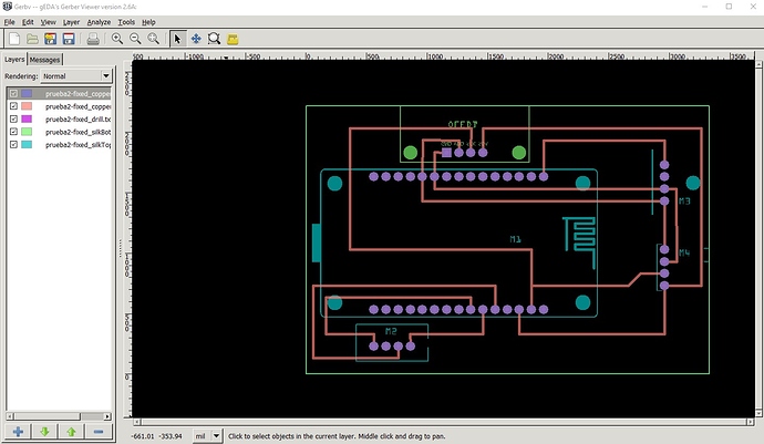
The gerber output for the board in gerbv
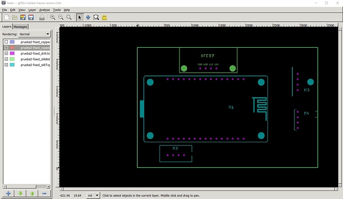
Gerber output with copper0 and copper1 not displayed to leave only the silkscreen and the holes. Note the holes are all the same size and all present unlike the earlier output.
That said here is a sketch of how I would do this board and why the changes.
prueba2-improved.fzz (90.6 KB)
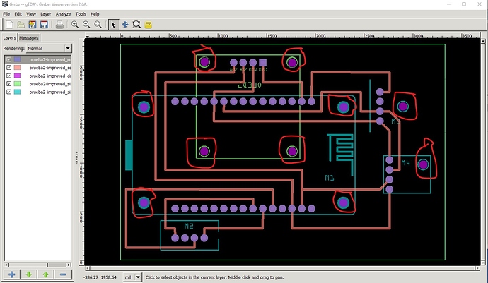
This is basically identical to the first one with parts moved around so there mounting holes are all on board and with holes dragged over the mounting hole in silkscreen. The major change is the OLED has been moved completely on board on the bottom of the board. This is because OLEDs are usually delicate and need to be secured so they don’t break. The mounting holes are drilled so you can secure the board with #2 screws. Similarly the FC28 hygrometer has been moved further in on the board so less of it is sticking out and its mounting hole drilled. Same for the BMP180, move it in a bit and drill the hole for its mount. The gerber output looks like this:
The holes circled in red here are the newly drilled mounting holes and the OLED is on the bottom of the board under the node MCU. As well as I think I noted earlier, unless this is being powered by the USB connector (and thus the USB port will always be connected), there is no power source for the board. If you don’t intend to power from the USB connector you need to arrange to provide a power source to the raw input pin.
Peter


