Hola.
He diseñado un circuito y no tengo claro si esta bien diseñado.
¿Como puedo comprobarlo?.
Un saludo,
Javier
Hola.
He diseñado un circuito y no tengo claro si esta bien diseñado.
¿Como puedo comprobarlo?.
Un saludo,
Javier
Upload the sketch (the .fzz file, upload is 7th icon from the left in the reply menu) here and some of us will look it over and point out problems.
Peter
via google translate
Cargue el boceto (el archivo .fzz, la carga es el séptimo ícono de la izquierda en el menú de respuesta) aquí y algunos de nosotros lo revisaremos y señalaremos problemas.
prueba.fzz (174.7 KB)
Thankyou.
Best regards.
Javier.
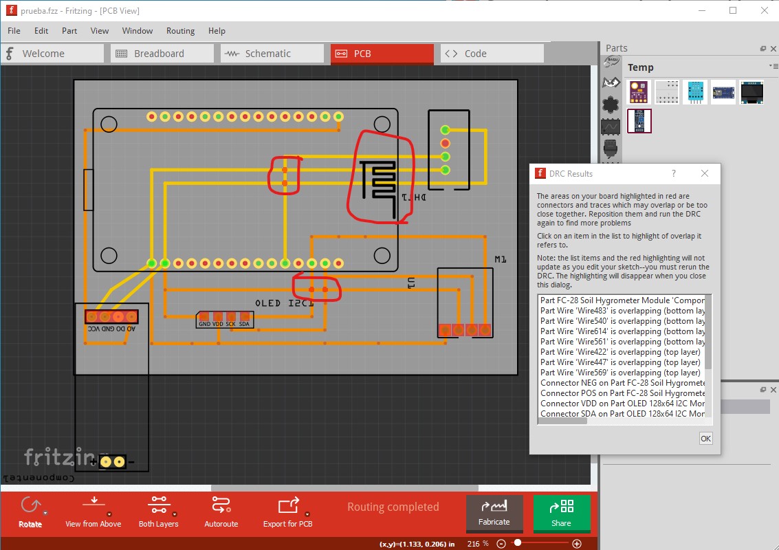
OK, a fair number of problems here. A number of them are because of poorly made parts though. First run DRC (Routing-> Design Rules Check) against pcb which indicates a number of errors:
The circled areas indicate problems. Traces on top or bottom layer can’t overlap. As this stands the traces circled in red are shorted together. As well the traces can’t go through the antenna area of the node MCU (they will affect the antenna on the board.) They should be easy to fix but many of the parts are poorly configured. I So to start replace the DHT11 part with the Humidity and Temperature Sensor DHT11improved.fzpz from here
which is better than the one in core parts (and in this sketch!) Replace the FC-28 part with this one:
FC-28 Soil Hygrometer Module-improved.fzpz (7.9 KB)
because the one in the sketch is broken. The OLED display part is also broken so replace it with the OLED-128x64-I2C-Monochrome-Display-GND-VDD.fzpz
part from here:
In addition double check that this is the board you have. As noted there are two common boards but with opposite pin configurations for power. If you have the other module, connecting it to the wrong Fritzing part will likely destroy it! For the bmp280 part use the one from here
as the one in your sketch is broken and won’t route on the bottom layer. This sketch has all the part substitutions made and contains all the corrected parts mentioned above.
prueba-improved.fzz (132.4 KB)
However one last point. How is the node MCU being powered? If the USB connector is connected, it will get power from USB. But if USB isn’t normally connected you need to supply a power source to the raw input pin for this to work. I would also suggest wiring this on the breadboard and checking that it actually works properly before ordering boards.
Peter
Gracias a todos, he reconstruido la placa y este es el resultado.
Ahora, ¿Cómo puedo confirmar que todas las pista estan en una sola cara?.
Os envio el esquema.
Un saludo,
Javier.
Thank you all, I have rebuilt the board and this is the result.
Now, how can I confirm that all tracks are on one side?
I send you the scheme.
All the best,
Javier.
prueba2.fzz (135.1 KB)
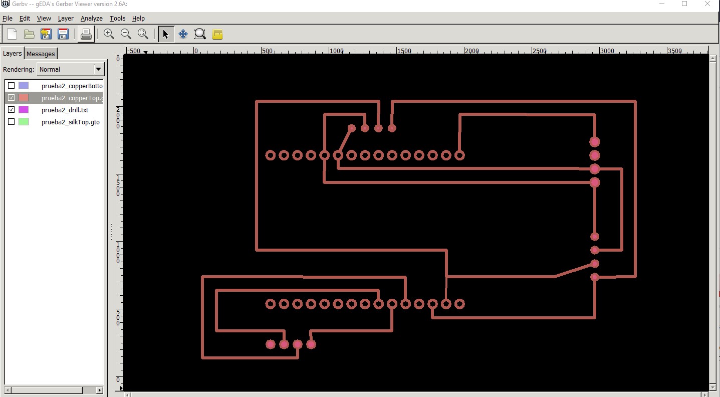
This has more problems than I thought. You are still using the old OLED part which is broken, but in addition (and which I didn’t notice before) so is the Node MCU part. It has no holes in the gerber output. As well the OLED display is set to be on the bottom of the board. Is this intentional? It would make sense if the OLED is to mount on the bottom of the board, otherwise it is a problem. Here is the top copper and drill layers from the gerber output
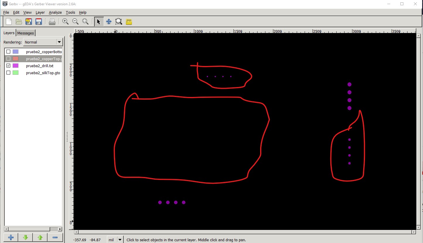
This is only the drill layer. The pins for the oled and one of the other parts (circled in red) are too small and all the pins for the node MCU are missing.
so the board won’t work as it stands. Do you have the model number of the node mcu you have? I will try and find a working part (there are lots around, but I need to know which particular model you have to select one.) In addition you may want to make the board larger and use the mounting holes on the various boards to be able to fasten them to the pcb. With parts extending past the pcb, flexing them may destroy the pcb unless they are bolted down.
Peter
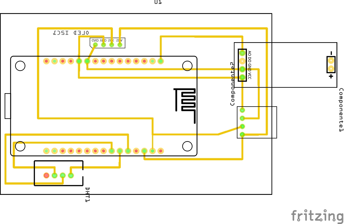
Thank you very much for your help.
I have changed the schema and it seems to be correct now, is it true?
![]()
Thankyou.
Javier
Unless you have changed the parts you are using (which are mostly broken), I don’t expect it will work any better. There are at least 3 widths of Node MCU (1.1in which is the part you have now, and which I have a corrected part for, 1.0in and 0.9in) so we need to know which board you have. The OLED needs to change to the part I referred to earlier, the one you have is broken and won’t work (the holes appear to be too small for starters) I’ll dig up replacement parts and post a more likely to work sketch in a bit.
Peter
OK finally some progress. I had to replace all your parts with corrected ones (including the BMT180 from core parts.) Here are where they are available:
Use the DHT11 part from this post as it is correct, and the current one is not.
Use this new corrected node MCU part (I didn’t do a complete cleanup on the original part in 2017)
The OLED part is from here:
Make sure the OLED you have is in fact a GND-VCC part rather than VCC-GND.
Use the FC-28 Soil Hygrometer Module-improved.fzpz part as the current one is broken. It was posted eariler in this thread.
Use this corrected part in place of the bmp180 in core parts (where pcb has incorrect hole sizes)
Barometric Pressure Sensor - BMP180 Breakout (GY-68)-core-fixed.fzpz (8.2 KB)
First your last sketch with correct parts added but no other changes. Now all parts have holes and all holes are 0.038in suitable for standard .1 header connectors (or the pins on the part as you choose.)
prueba2-fixed.fzz (89.6 KB)
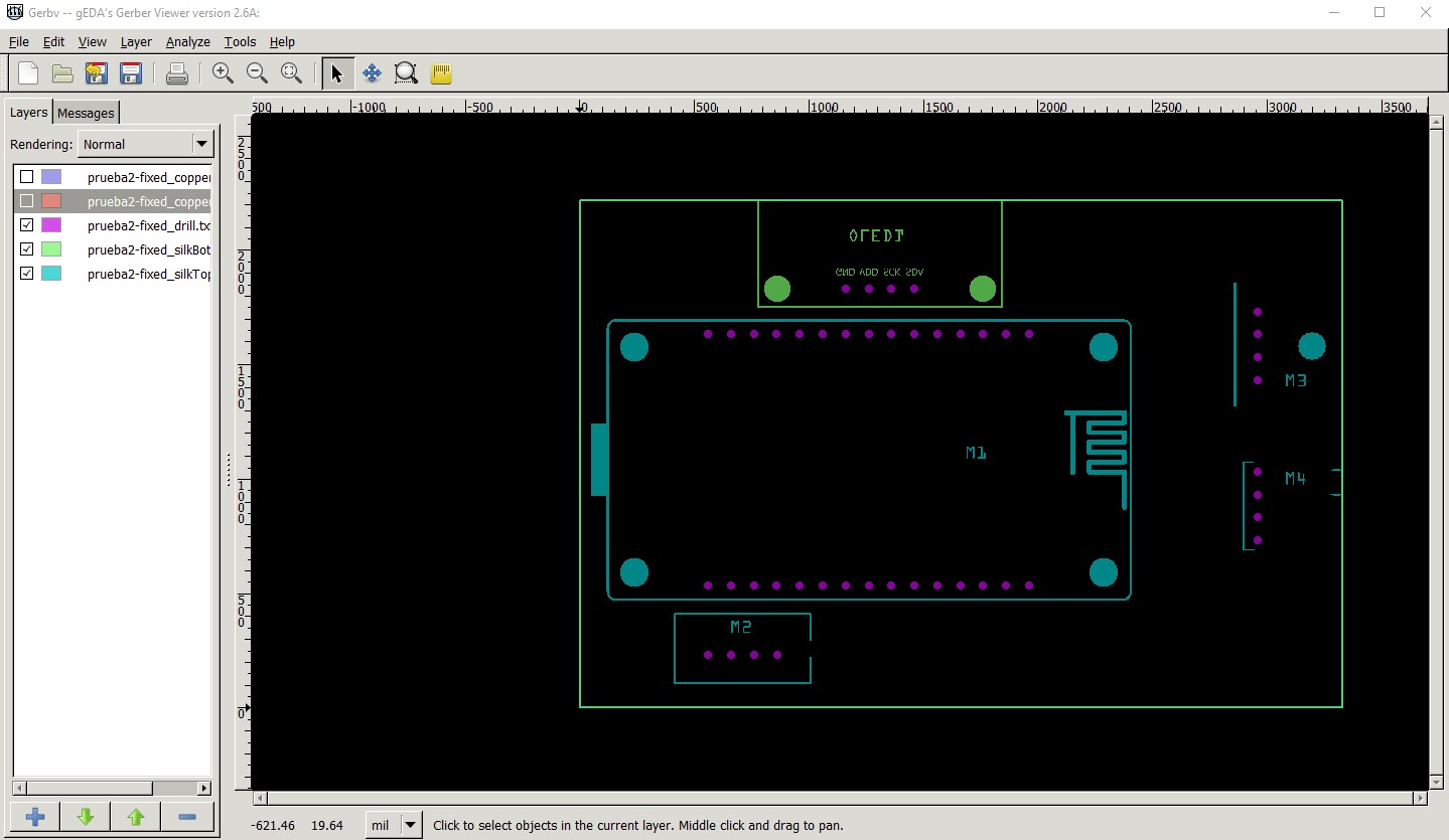
The gerber output for the board in gerbv
Gerber output with copper0 and copper1 not displayed to leave only the silkscreen and the holes. Note the holes are all the same size and all present unlike the earlier output.
That said here is a sketch of how I would do this board and why the changes.
prueba2-improved.fzz (90.6 KB)
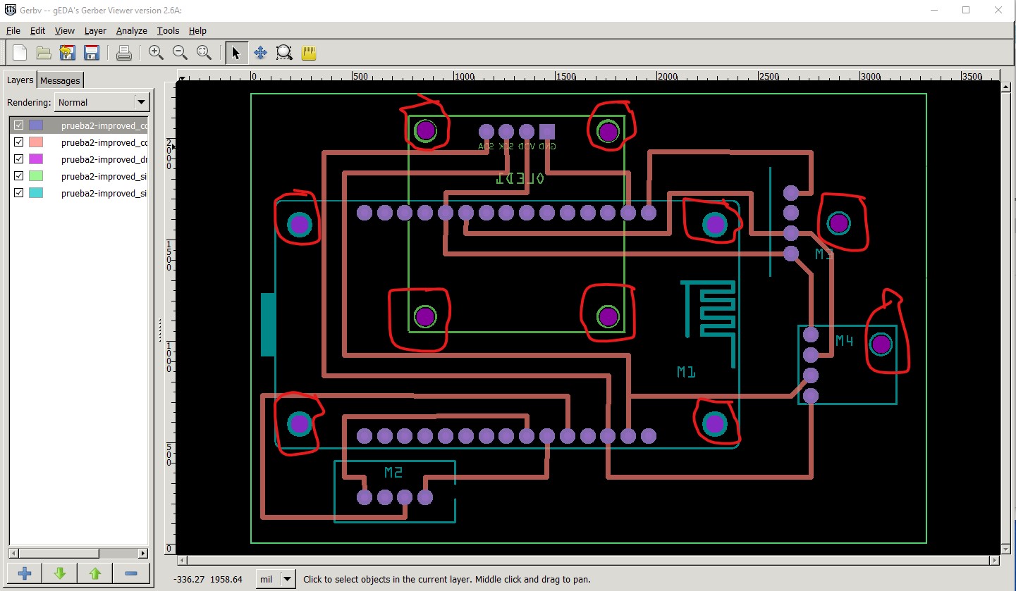
This is basically identical to the first one with parts moved around so there mounting holes are all on board and with holes dragged over the mounting hole in silkscreen. The major change is the OLED has been moved completely on board on the bottom of the board. This is because OLEDs are usually delicate and need to be secured so they don’t break. The mounting holes are drilled so you can secure the board with #2 screws. Similarly the FC28 hygrometer has been moved further in on the board so less of it is sticking out and its mounting hole drilled. Same for the BMP180, move it in a bit and drill the hole for its mount. The gerber output looks like this:
The holes circled in red here are the newly drilled mounting holes and the OLED is on the bottom of the board under the node MCU. As well as I think I noted earlier, unless this is being powered by the USB connector (and thus the USB port will always be connected), there is no power source for the board. If you don’t intend to power from the USB connector you need to arrange to provide a power source to the raw input pin.
Peter