As I expected, your node mcu part is misconfigured. The pads are ellipses which causes the gerber code to not drill holes:
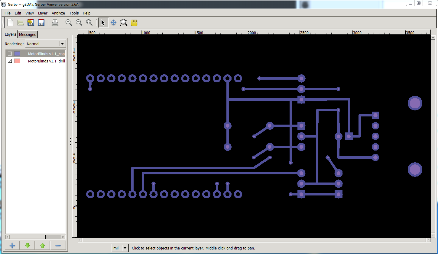
This is the gerber output of your sketch in gerbv with copper bottom and drill layers loaded. Note the pads outside the node mcu have a lighter circle (which indicates a drill hole) that is missing in all the node mcu pads. That is caused by this in the pcb svg file (loaded in Inkscape):

The rx and ry circled in red on the right should be a single r with a value of 2.6 to make a hole. So for this fixed part I changed all those from rx/ry to r 2.6 which causes the new part to drill the holes correctly:
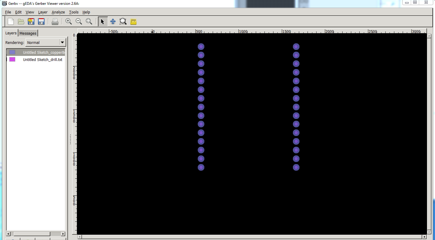
again gerbv output with copper bottom and drill layers (but only the node mcu.) This is the part you need:
edit: May 2021 I had occasion to use this part again and corrected some more errors in silkscreen. I have replaced the old part with a new one.
ESP8266 NodeMCU LoLin module-fixed.fzpz (46.5 KB)
It has the same moduleId as the current part, so in your sketch you will need to do a “delete minus” on the node mcu part which does this:

deletes the part but leaves the traces in place. At this point I saved the .fzz file because sometimes Fritzing doesn’t correctly remove the part completely and won’t load the new part. I opened it again and loaded the new part (which is now in the mine parts bin.) In this sketch that is all that has been done (so if you wish you can try the rest of this to learn how to do it):
MotorBlinds v1.1-fixed.fzz (28.6 KB)
Starting from here I moved the new part in to position on breadboard (rotating it to get it aligned correctly):
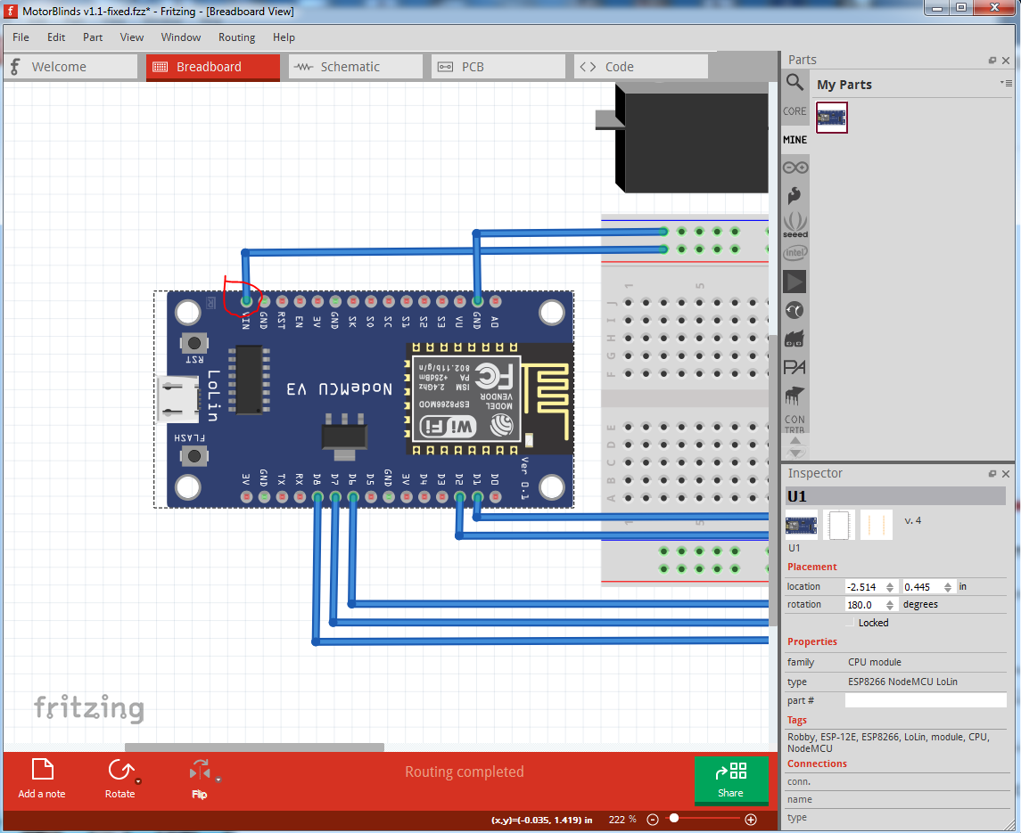
unusually for me (this is usually difficult) the part connected as it should as indicated by the green (connected, as opposed to a red not connected) circle in each connection. To achieve that you need to move either the part or the wire a bit so that Fritzing makes the connection. So breadboard is done. Now on to pcb.
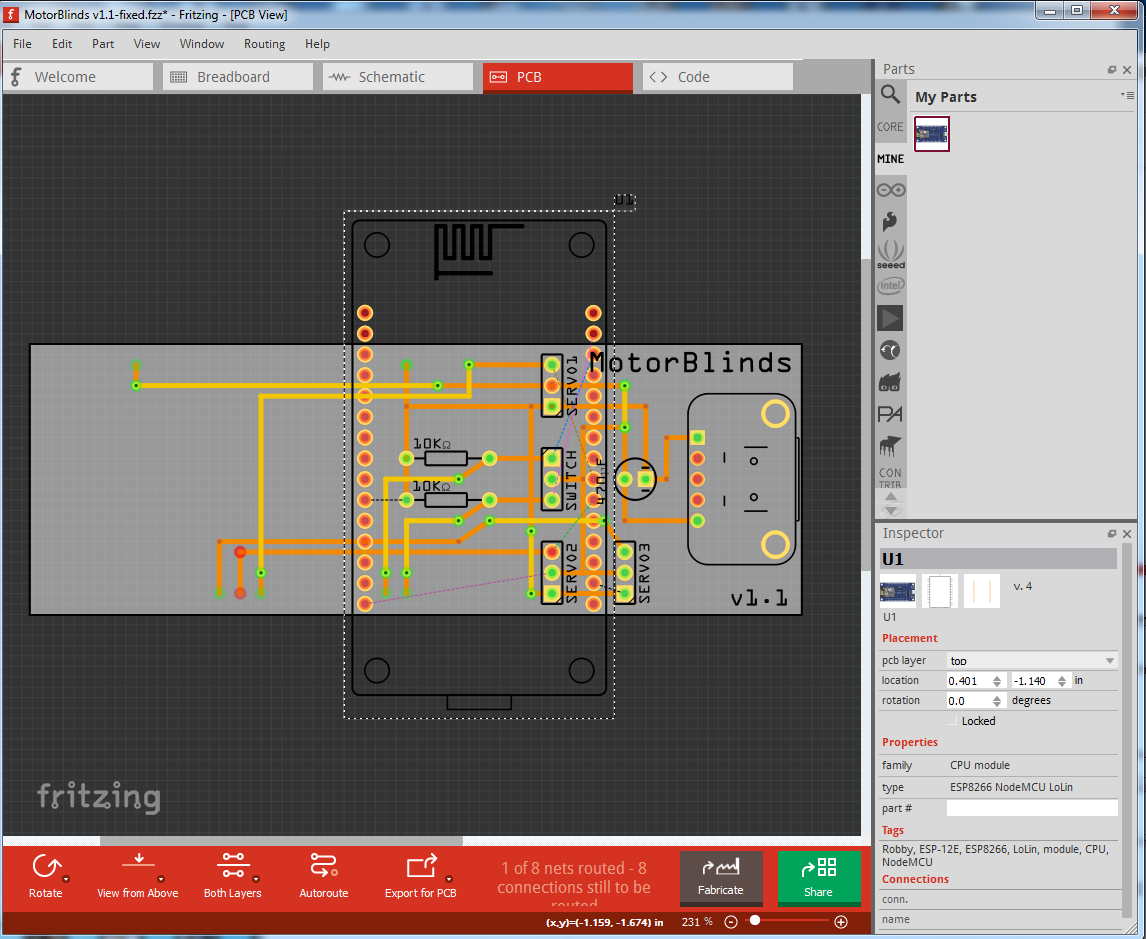
Here again the part needs to be rotated and moved to the correct position:

Here we see all the connections still have red circles (indicating no connection) and we have rats nest lines indicating where Fritzing thinks connections should go. Unfortunately Fritzing will prefer to select rats nest lines and make new connections which is not what we want so here I clicked View->Rats nest layer to disable the rats nest lines so they won’t select. Because all the traces are on the bottom layer I also selected bottom layer at the bottom of the window:
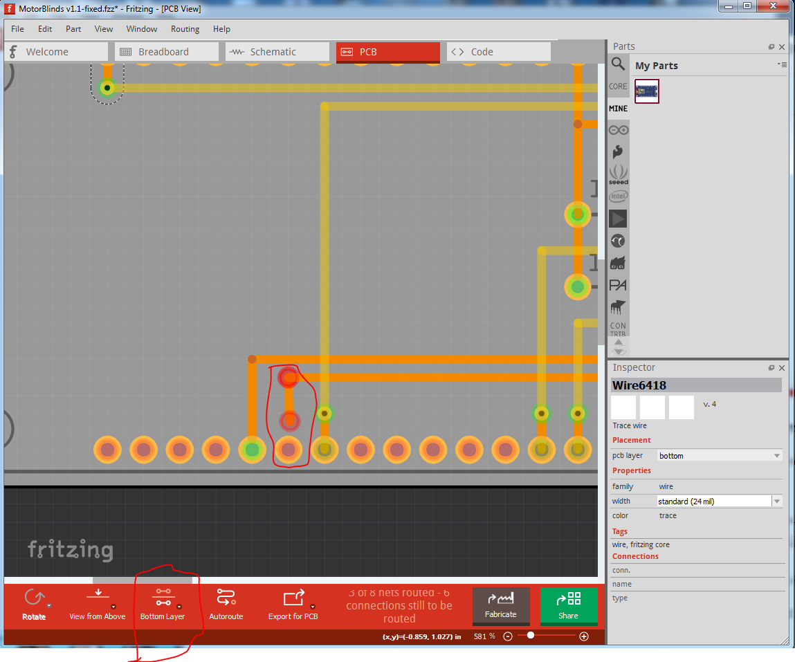
Here I have moved a couple of traces (green circles) to reconnect them and dragged one trace back a bit (circled in red) to indicate how to drag it down to the connection to make the connection.
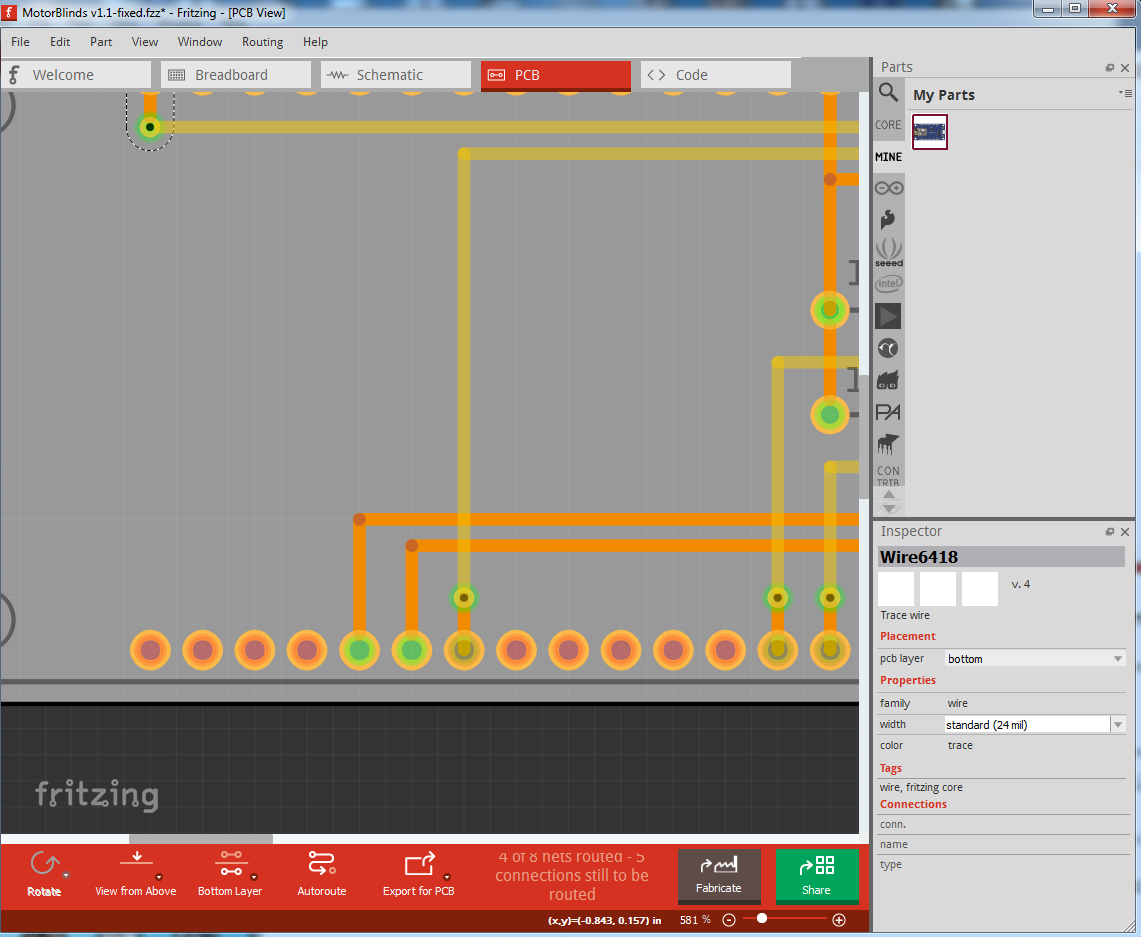
After re making all the connections (as indicated by the routing complete message at the bottom of the screen.)
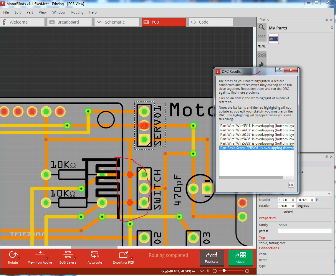
I ran DRC (Routing->Design rules check) which points out several problems: the trace circled in red is shorting the two connections of the switch (which breadboard indicates shouldn’t be shorted.) It is also unhappy about the trace going through the middle pin of the servo, assuming it should be connected that way, the correct method is for the left side trace to terminate at the servo pad and the right side trace connect from the servo pad to the next connection.
edit: forgot the final .fzz file …
MotorBlinds v1.1-fixed-2.fzz (115.4 KB)
Peter