I apologize in advance for the kind of question I’ll be asking but I really just need help with how the wirings are supposed to work. I’m not sure how are they supposedly placed on the breadboard as I am a complete beginner relying on tutorials and basic instructions/knowledge I’ve gained by looking through various sites for insight. If anyone could look into this and provide me somehow suggestions or simply correction on how should they be placed or what I need to do further. Thank you!
Your best bet is to upload the sketch so we can look at it in Fritzing. You need the .fzz file that you saved the sketch in and upload is 7th icon from the left in the reply menu. Off the top you may need a better power source, the Arduino can generally only supply a small amount of external current (about 50ma I think) and that may not be enough for the relay.
Peter
Peter
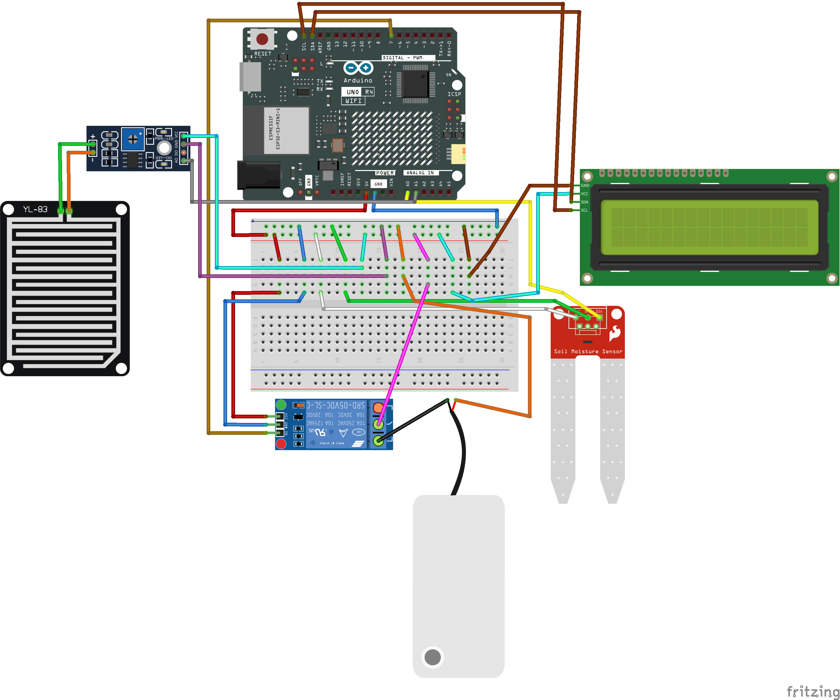
Good day! here’s the sketch I’ve made:
and to follow up, which power source can i get for this project? initially, i have only intended to use a plug to the barrel jack of the Arduino that’s 12V. I’m not really familiar with any other materials that i can use so i hope you can help me
Untitled Sketch.fzz (149.1 KB)
50ma at the data pins, but you can get more than that (a few hundred) out the power regulator by connecting to the 5V pin. That is the total, including what is being used at the data pins. The voltage regulator has a limit, which varies depending on the input voltage (at the jack). Higher voltage means the regulator gets hotter for the same needed current, so you will not be able to use as much at the 5V and data pins with 9V in as with 7V in. The input needs to be enough higher than the regulated (5V for a standard UNO) voltage for the regulator to work. That varies depending on the regulator, which is specific to the Arduino board model.
He is using an Arduino Uno R4 Wifi board. Its docs don’t exactly say how much output at 5V is available only that it is not expected to drive servos. I believe the Uno has a limit of around 50ma on the output 5V pin the rest being used internally. In this case he has a relay and a water pump which I expect are going to draw too much current to be supported by the Uno R4 Wifi. I’ll see if there is a schematic for the Uno R4 Wifi (I expect there is) and see what we can do from there. A larger 12V wall wart and possibly an output buck regulator may do the job.
Peter
For me I usually do my projects on an uno R3. I guess it should work as well? ![]() Then maybe I can help you
Then maybe I can help you ![]()
I expect he wants to use the wifi. I expect a buck regulator off the 12V input will supply the necessary current for the relay and pump although @kuyuley the specs (especially voltage and current draw) for the pump would be useful, I should have the specs of the songle relay around somewhere if not they are online.
Peter
OK, first thing to note is this from the Arduino R4 Wifi docs:
" Maximum current draw per pin: the UNO R4 series’ maximum current draw per GPIO is 8 mA, which is significantly lower than previous versions. Exceeding this limit may damage your pin / board."
The Arduino Uno is capable of 40ma per pin and many of the modules depend on that. What that means for you is that you likely need a driver on the relay module to boost the output current because the relay module has an opto isolator and likely wants about 20ma of current to operate (which is above the 8ma the R4 can provide!) As well we need more information on the pump you are using, specifically what voltage it wants (12V, 5V, something else) and how much current it draws. A data sheet for the pump should provide all that information. From there we can figure out how to power both of them, it should be possible to power the whole thing from the barrel jack input pin (it corrects directly to the VIN pin of the R4 from the schematic) but the wall wart may need to have a larger current capacity depending on how much current the pump needs (for which we need the data sheet on the pump!) It looks to me like you mostly need a transistor to drive the relay (or replace the relay with an SSR which has no mechanical parts unlike the relay or with a MOSFET which again depends on the specs of the pump.) So if you can provide the specs on the pump we can proceed.
Peter
I see. I could only comprehend a few points you’ve made but the mini DC water pump I intend to use in this project needs 5V as its current. Just an additional question, if the mini dc water pump that I have only needs 5V, would a 12V wall wart will be enough to power the whole setup or do I still need an external power source specifically just for the mini DC water pump for it to run?
Here are the specifications for the pump:
Mini Submersible Pump 3-5V
This Mini Submersible Pump 3-5V is great for experiment, aquarium, and fountain etc. It is suitable for varieties of water such as city water, ground water and sea water.
Specification:
DC Voltage: 3-5V
Low Noise
Maximum Lift: 40-110cm / 15.75″-43.4″
Flow rate:80-120L/H
Outside diameter of water outlet: 7.5mm / 0.3″
Inside diameter of water outlet: 4.7mm / 0.18″
Diameter: Approx. 24mm / 0.95″Length:Approx. 45mm / 1.8″
Height: Approx. 33mm / 1.30″
Material: engineering plastic
Driving mode: brushless dc design, magnetic driving
Continuous working life of 500 hours
The pump doesn’t have a current spec which we need. Do you have a web site for the pump? From that I may be able to find a current draw indication somewhere. A google search for “Mini Submersible Pump 3-5V” turns up this one
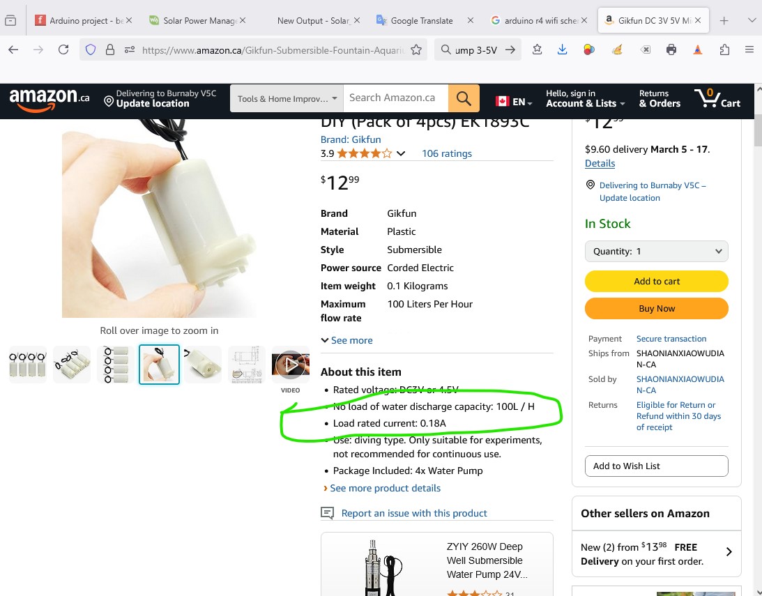
which tells me what I need I expect, the pump needs about 200ma to run. A 12V wall wart should easily run that and a MOSFET module should be able to replace the relay. You will need to add a buck regulator to reduce the 12V to 5V for the pump but that is easy. The MOSFET board also removes the need for a driver (they draw less than 8ma of current.) A Fritzing part is available here
you would then need to find such a module to but but I expect that should be fairly easy. For the buck regulator there are two choices, first a fixed voltage one like this
and an adjustable one such as this
the advantage of the adjustable one is that you can set the output voltage via a screw driver adjustable pot on board. That would allow you to change the volume of water your pump outputs (at least between 3 and 5V, higher than that may damage the pump!) For the parts of the replies you don’t understand feel free to ask for clarification and I will try and explain. I don’t mind answering questions when something is unclear, in my opinion the only stupid question is the one you don’t ask because you think it is stupid ![]() . This stuff is generally fairly complex and has limitations (such as the Arduino current draws) that are not necessarily obvious if you don’t know about them.
. This stuff is generally fairly complex and has limitations (such as the Arduino current draws) that are not necessarily obvious if you don’t know about them.
Peter
Okay, so here’s the link of the website where I purchased the mini DC water pump:
As for clarification, I’ve come to understand most of the parts now but my question is how do I change the volume of the water pump if I use the mini 360 dc-dc buck converter? And would it be a bother for you to layout it into the file i sent here since I don’t really know how the connections work. I didn’t expect this project to be this complex (for a complete beginner) as I have only have weeks left to finish it up. Also, if I use the mini 360 DC-DC buck converter, would i still need the step down voltage regulator or not?
That site doesn’t list a current value, but it appears the same as the amazon pump and thus likely has much the same current draw I expect.
turning the pot on the min 360 changes the output voltage (unfortunately in a very non linear fashion so you need to be careful, as with a 12V supply it will go up to 12V which would likely damage the pump.) Changing the voltage between 3V and 5V will change the amount of water that the pump produces (higher voltage more water flow) Note if you actually build this you need to connect the mini 360 without connecting the pump, power the mini 360 and then set the voltage with the pot to be 5V and vary the pot down to 3V (the minimum specified for the pump) and only move the pot between those two positions to protect the pump. A safer version would be a Polulo D24V5F5 which will only generate 5V (so won’t change the volume of water, but also won’t over power the pump.) There is a Fritzing part for the D24V5F6 which has the same pinout. It would connect the same (but on different pins) as the mini 360.
The mini360 is a buck step down regulator so they are one and the same. Do you have to actually build this project or is this only a design exercise? If it is a design exercise you can likely get away with the current circuit as it will work (in real life it may have problems for the R4 though.) Here is your sketch with the mini 360 added to it, I didn’t replace the relay with a mosfet as you would need to select a part to use (either a module which is likely easiest) or a MOSFET from core parts which means you would need to pick the mosfet you are actually going to use.
Untitled-Sketch-mini360-added.fzz (159.6 KB)
Peter
How do I exactly power the mini 360? Do I just follow the file you’ve sent? And yes, I do have to build this project ![]() .
.
It will get 12V from the VIN terminal on Arduino (which in turn is connected to the the barrel jack where the 12V to power the Arduino comes in. As long as you have 12V plugged in to the barrel jack this should work as far as I can see. I think the shutdown pin on this part should be able to eliminate the relay module You would need to try it to see if I am right. The shutdown pin when low will shut off the regulator. The will stop the motor. Setting shutdown high will turn the regulator on and as long as it will start the pump should do what you want. The D24V5F5 is fixed at 5V so you won’t be able to change the volume of water pumped, but given how sensitive the pot on the mini 360 is that is probably safer (there is a good chance the pump would burn out on 12V!)
In addition there is a 1n4004 diode across the pump to take care of back emf then the power supply goes off. I think this should work, but trying it will be the only way to know for sure. As before the gets 12V from the VIN pin of the Arduino. The
Untitled-Sketch-D24V5F5-added.fzz (139.4 KB)
at worst you have to add the relay back in if the power supply won’t do the switching.
Peter
If I were to use the mini 360 and still im unsure of its safety to the pump as it could over produce voltage, would it be better if I just change the pump itself to a 12V water pump? or would it draw too much mA? the D24V5F5 is too pricey for me and i only have a matter of time to assemble it all. would you further elaborate too on the diode part?
1 Like
That should do what you want and eliminates the mini 360 as well you would need the relay and a transistor driver for it but that is easy. You would need to check the specs of the pump you buy to see how much current it draws, if it pumps higher water volumes it will likely draw more current, but there may be equivalent 12V pumps to the one you have that should take less current (if the water flow is the same the current shoulsd drop with higher voltage.) The diode is back emf suppression from the motor, when the power supply turns off. The inductance of the motor will produce back emf (which may damage the power supply) when it turns off.
Peter
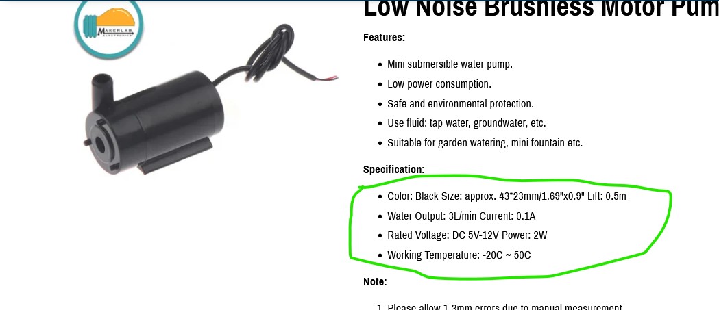
I see, so let’s say this is the pump I would use:
Would it be compatible? And do I use the same relay I used in the first sketch or another type of relay? Can you also suggest a type of transistor driver that I could use? I’m really sorry for asking for so much questions I don’t have anyone who’s knowledgeable about these kind of projects and I really have to make sure whether the materials are right so I don’t damage the Arduino (it’s pretty expensive in my country).
Yes the pump should be fine. It isn’t clear at what voltage they are doing the 100ma measurement I suspect 5V which means at 12V it may take 200ma (and pump more water) but that should still be fine as long as your 12V source can provide about 1A of current which I expect will provide the pump and all the other circuitry.
to use the relay you will likely need to add a transistor driver like this
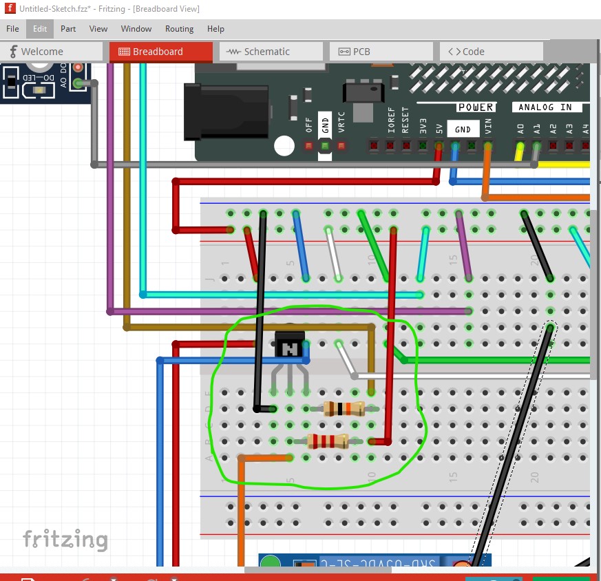
this is set for a 2n3704 transistor (which is ecb, emitter, collector, base) but most any npn transistor with a gain of 100 would do so whatever you can get easily. For a different transistor you may need to change the pin layout if it is not emitter, collector, base in Inspector. This is the sketch with this change.
Untitled-Sketch.fzz (151.5 KB)
Peter
Okay, so I just need that kind of pump, a transistor and are those resistors? Can you specify which kind of resistors are they then I’ll just check further when I buy one. Also, could a 2N3904 be an alternative for the transistor you gave? how will the pin layout will change?
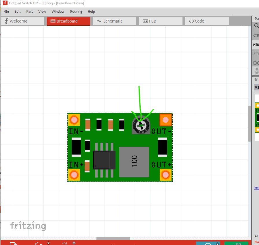
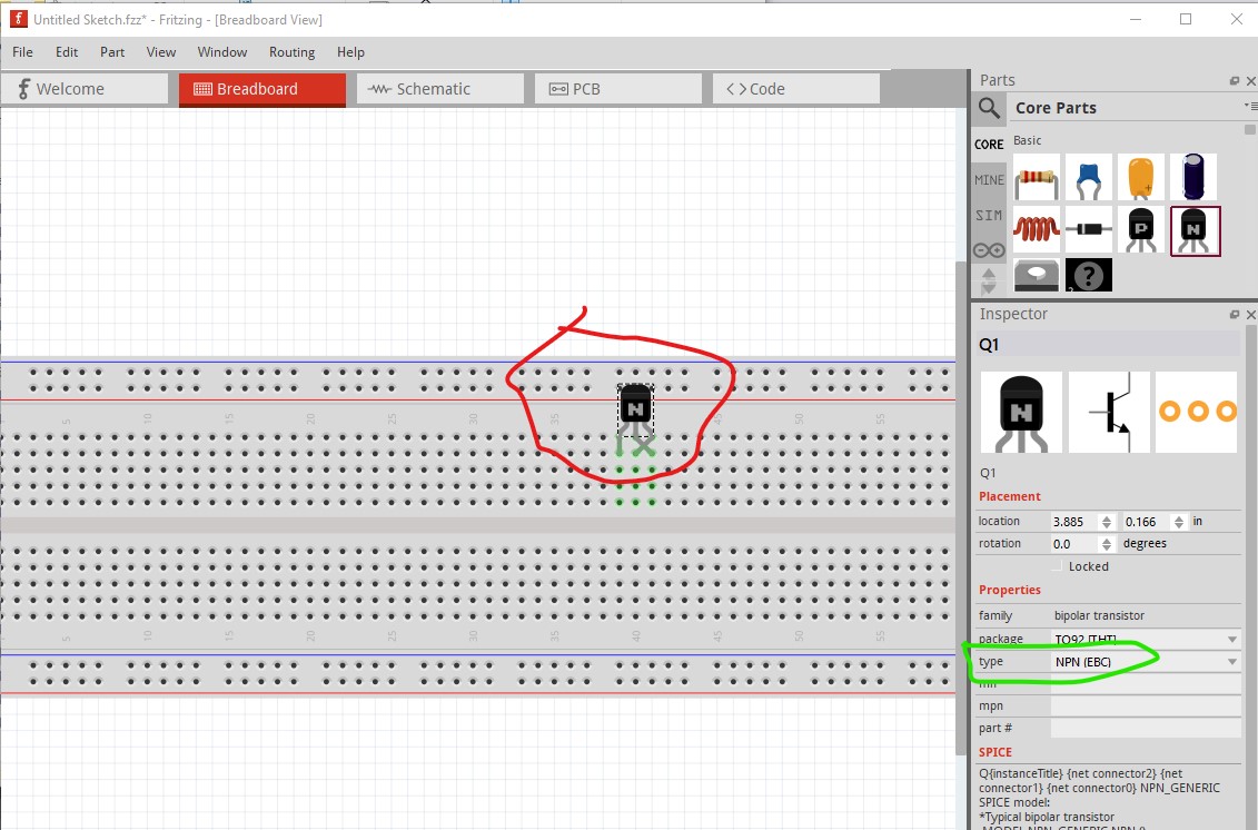
Currently the resistors are 2k2 and 10k, but they could both be 10k without a problem they usually come in a bag of 10 or so. Yes a 2n3904 will be fine. the easiest way would be to delete the current transistor then drag a new one in from core parts, This is the current transistor (ecb)

it is possible to change that in Inspector to ebc in Inspector
but it swaps the pins around which will screw up the connections so you are better off to delete the current transistor (select it and press del) then drag in a new transistor which is by default ebc
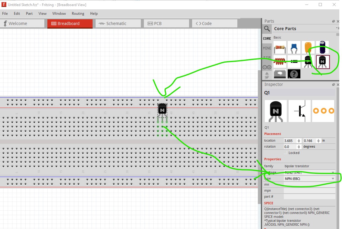
you will then need to move the resistors and wires connecting to the transistor to the same pin (base emitter and collector) on the new transistor. I would install the new transistor on an empty area of the breadboard then move the wires and resistors one at a time to their new position. If you hover over the transistor pin it will tell you what pin this is like this move the mouse to where the green arrow is and it will tell you the pin name
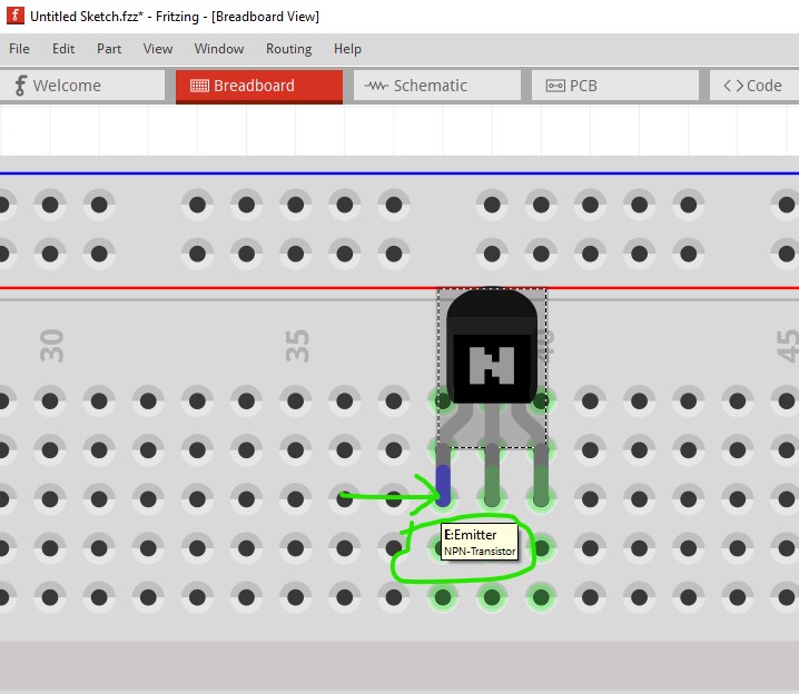
the emitter in this case. So move everything connected to the emiiter to the new transistors emitter.
Peter