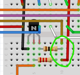
To clarify, where does the brown and red wire connect to? in the fzz file they seem to connect in the same resistor, or was it supposed to be that way?
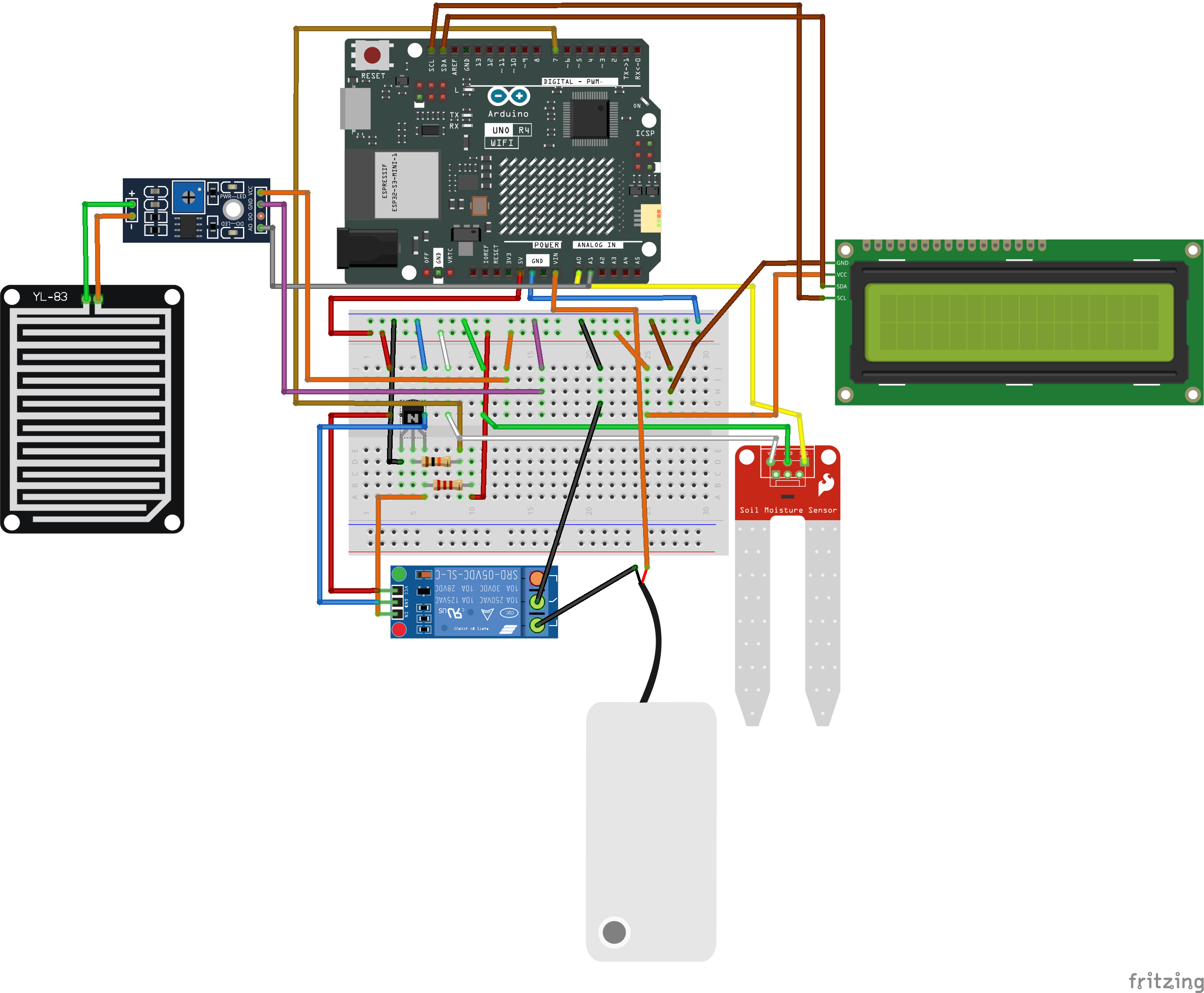
I just apply the same layout when actually building the project right? Thank you so much for the help! If there’s anything more that I can ask I’ll just leave further questions soon. For now, this is all I need, thank you once again!!
Error on my part (and good catch!) it should be over one pin and connect to the resistor like this to provide a 5V pull up on the collector. The way it is now would not work (and likely damage the data pin on the micro!) so check twice before powering up a circuit.
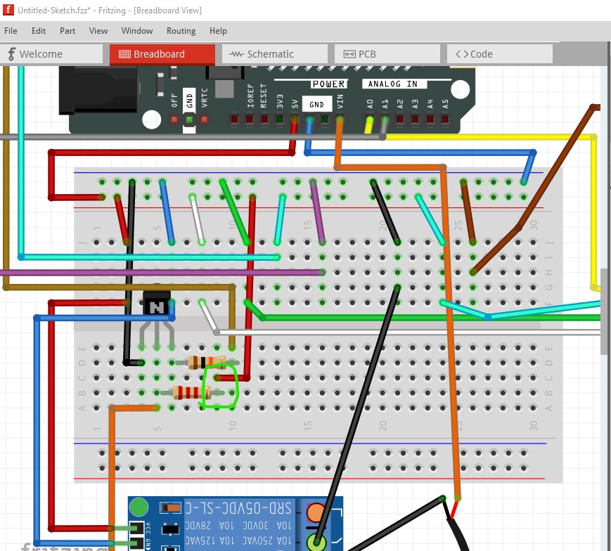
that is why it is always a good idea to route schematic. Schematic makes mistaken connections easy to detect when wires go somewhere you didn’t expect. Yes wiring the breadboard exactly like this (assuming breadboard is correct) should be what you need to do.
Good day! Alright, just to be sure here’s the updated wirings based on what I’ve understood from your directions. I’ve already switched to ebc from ecb, and the connecting wires were placed on where they last connected to (whether it was in the base or the collector).
I just want to make sure if it’s good to go. As for building the project physically, I’m currently waiting for the pump to arrive and I’ll be testing it out right away. Thank you once again.
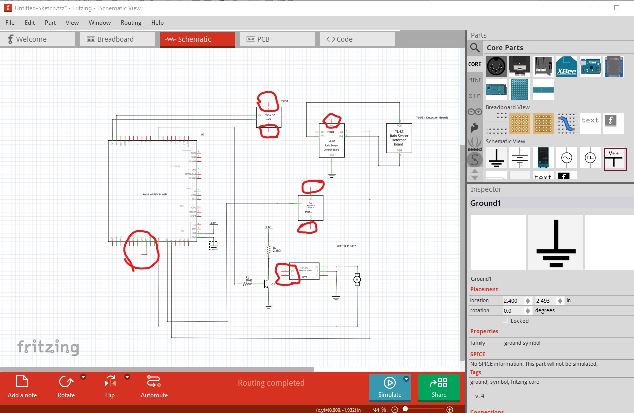
There is a short (which I can’t see the cause of in breadboard) between 3V3 and 5V. Then several of the boards lack connections to VCC. The sketch with schematic routed
right clicking on a pin in breadboard (or any view!) will light all pins connected to a network. Here it shows the connections that are not there. Moving the wires may get them to connect and correct schematic.