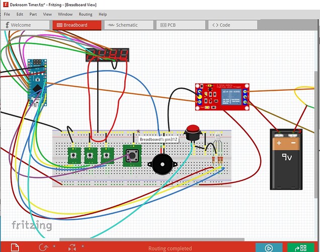
This the first time I try to make a circuit. Maybe I’m aming to high. But can someone check my work?
Darkroom Timer.fzz (65.3 KB)
You have a number of problems (and some issues which may be intentional.) The issue that may be intentional is that all 4 digit selectors on the LED display are grounded. This has two implications: all the digits will display the same (i.i.e 1111 or 3333) and you need typically 20MA to drive a segment. Times 4 that is 80MA per output pin and the Arduinos can only provide up to 40MA per pin so if you intended to do this you need higher current drivers in the path. Now on to the errors that I see.
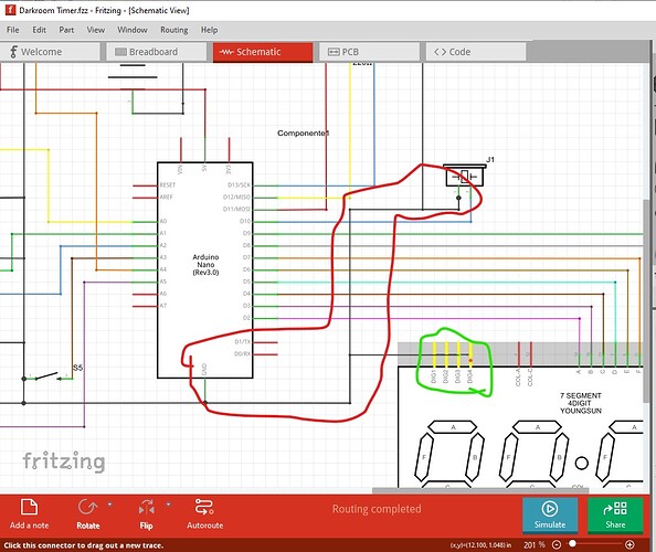
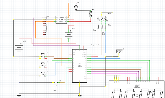
Here in schematic view I left clicked on a select pin of the display (which selects one of the digits) everything connected to it lights yellow. Unfortunately in this case that is only the 4 pins on the LED display circled in green) there is no connection to the circuit ground which there should be (circled in red).
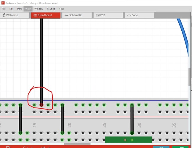
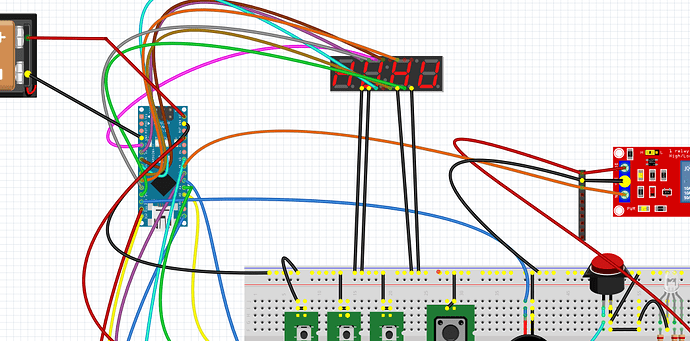
In breadboard the connection to the LED display (circled in red) is not connected to the breadboard (note that the connection point is red not green like the rest in the image.) Moving the wire should correct that (and then cause a rats nest line to appear in schematic view!)
here I clicked on one pin on ground on the breadboard. Note that the pins on the LED display on the top do not light as they are not connected (circled in red.)
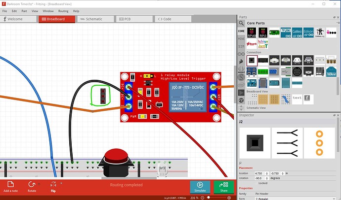
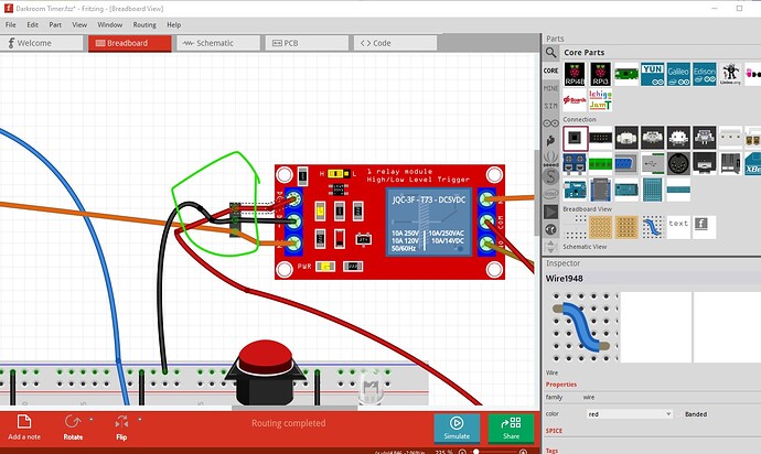
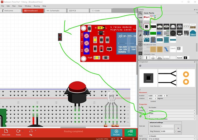
Then because the relay part has no pcb, you need to add a three pin header to produce pads in pcb to connect the wires from the pcb to the relay board like this (circled in green):
Then connect the wires through it like this
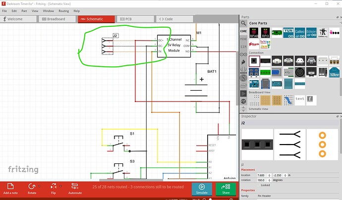
Now you will have three pads to connect the wires that go to the relay board in pcb. In schematic you now have a new connector that you need to connect. They are connected by rats nest lines as the connections were made in breadboard.
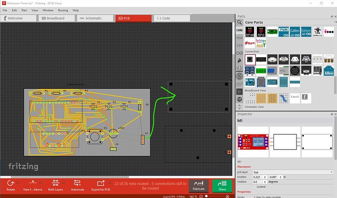
similarly you need to place and route the header in pcb to provide the needed three holes to connect wires to
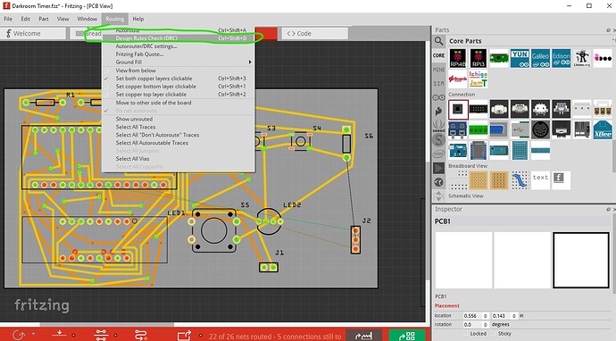
Those three pins will be wires connecting to the relay board (green arrow!) Then in pcb view you need to run DRC to check the pcb routing
It flags a bunch of errors
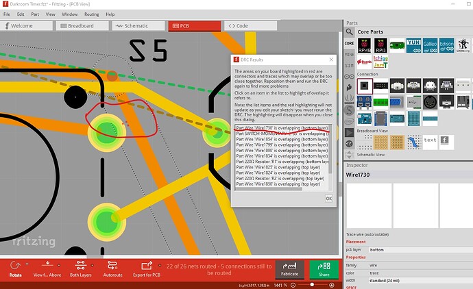
Here I clicked on the first entry in the DRC report and it highlights the connection involved and shows by the three red dots circled in red that the bottom layer trace is too close to the pad so the trace needs to be moved a bit further out. The other reported errors need to be dealt with similarly. You should always run DRC on a finished sketch to make sure the board is producible. Hope this helps, post again if you have questions.
Peter
HI,
Thank you very much for the input. I grounded these 4 pins because I supposed that the LED display must be grounded. The error is not intentional. Since it´s a countdown timer, I want to be able to select hours, minutes, seconds and fractions of a second. Does the dsiplay need to be grounded? If so, where do I ground it?
Now for my various errors:
I cleaned up the schematic and hopefully fixed some errors.
I connected the 4 pins to ground and checked that everything else is connected too.
On the breadboard, I checked that all connections were green.
Clicking on a pin, all connections were lighted.
I could not find a three pin header like yours. I used a 10 pin, but it does the work. And also did the connections on the schematic.
On the PCB I have corrected only one overlapping which fixed all the other overlapings. So after running DRC it says it’s Ok for production.
Would you check it again?
Darkroom Timer1.fzz (68.0 KB)
Thanks
JP
Hi Peter,
I posted a reply, but I do not know if you had the opportunity to see it. Thank you very much, your input was very helpfull.
I think I fixed all the issues. This is the first time I use a breadboard and I have not done a shematic since my Highschool years. Obviously this my first time using Fritzing. Now I have to learn how to program the microcontroller.
Darkroom Timer1.fzz (68.0 KB)
Thanks again,
JP
OK, you have a few problems which are corrected in this sketch (I think, to be sure you need to breadboard the real circuit and make sure it works!)
Darkroom Timer2.fzz (67.5 KB)
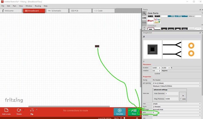
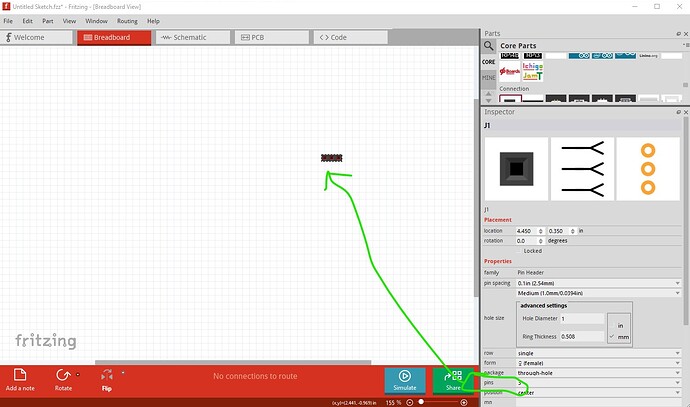
Since I needed to make changes I re wired breadboard in a more readable form. First your 2 pin header is available from the generic header like this:
first drag the part in to the sketch then change the number of pins from 2 to 3 in Inspector like this
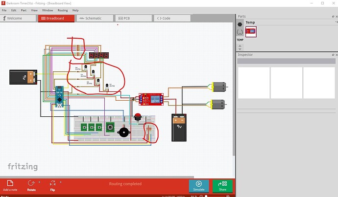
Here is the new sketch
Darkroom Timer2.fzz (67.5 KB)
With these changes/additions
First current limiting resistors on the segment lines, then pnp transistor drivers on the digit select lines which now go to I/O ports (as they need to be selected.) This display is multiplexed. That means that you write the 7 segment value to the digit, then select (by pulling the output port from the default all high to low on the digit you want to display) the appropriate digit then lights up in the correct place (with all 4 select ports grounded all digits would have lit the same and drawn too much current!) You then need to repeat this in your code on a regular basis (there should be examples in the arduino forums of how to do this!) As noted before all the current for all 7 segments flows through the select pin so that is what needs the transistor to protect the I/O port (which is limited to 40ma of output current.) Finally your three color led is common anode and thus needs to connect to 5V to operate (not ground.) I didn’t do anything about pcb at this point because you may want to move things there around. Another problem (that I don’t have a fix for) is that as it stands one or the other of the motors will always run. Because when the relay is powered off the NC to common connection (and thus the motor connected there) will run draining the battery. You need something like a power switch in the common line of the relay to be able to shut the battery off when not in use. As well are you intending to use batteries or do you want an AC power supply? There are generic AC powered supplies available in this forum post:
Hope this helps, if not feel free to ask further.
Peter
Thank you very much Peter,
The schematic looks fantastic and much more cleaner than what I did.
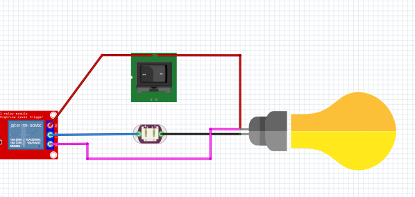
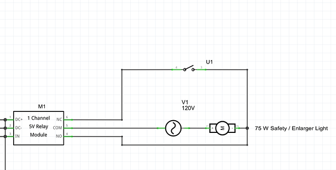
With the relay, I’ll be working with 110V AC. Since it is for the Darkroom, I need to switch from the safetylight to enlarger light. The Safety light should turn off when I use the Enlarger light, and adding an extra switch works fantastic.
I changed this part to only use one light, but with both relays. That way I can use the safety light to prepare the negative for printing (focusing) and then the enlarger light function for printing the negative.
I had tu use the motor component, because I could not find a 75 W light bulb.
I will get a breadboard to make sure it works.
Thanks again!!!
JP
google is your friend, a search for “fritzing part light bulb” turns up this forum post:
as well as a 220V bulb I found for someone here
in general a google search for “frtizing part part_description” is a good place to start. In .fzz (sketch files) the temp parts bin will have custom parts that are not in core parts that people have made. Right clicking on the part in the temp parts bin and selecting “export part” will give you the .fzpz file for the part.
Peter
Thanks got the components.
