Install Inkscape 0.92.4 (or more current version, 1.0 is in beta now but not stable enough to use)
Start Inkscape
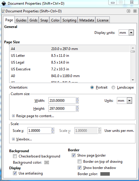
select File->Document Properties
which gives this as the default starting point. I do not know how (or if it is possible) to configure this in the preferences file or other config file, so it will open with a different default. If someone does, please post.
change this to:
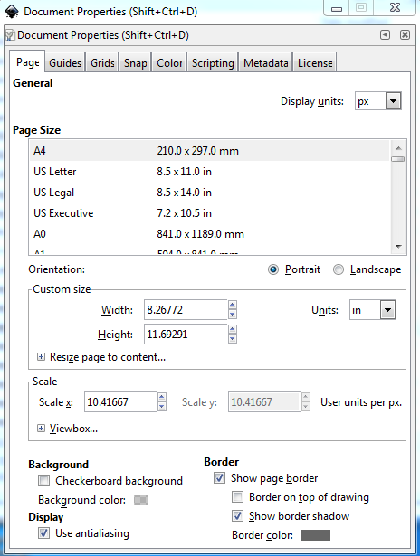
unfortunately you need to do this for every document from the gui it appears. In the case of an existing svg file, the two unit changes should just work, but if the scale is not 10.41667 you will need to rescale the document in which case see
Now change the Inkscape preferences (this only needs to be done once, and will be written in to the preferences.xml file for later invocations)
Open Inkscape and click Edit->preferences
click on the + before Interface to expand the menu to get to Windows and Grids
Edit->preferences->Interface->Windows->Default window size from Maximized to Large
I prefer to open with a window that isn’t full screen, but large, pick which you like.
Edit->preferences->Interface->Grids
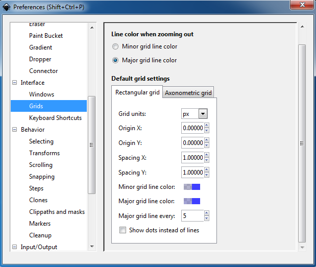
and change it to this:
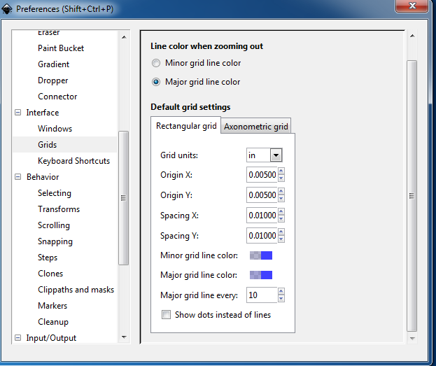
Units Inches
x and y offest of 0.005in so a 10 thousandth inch wide line in schematic will be centered on a grid line when it is on a 0.1in boundary. This makes visually checking alignment easy. You can change this from the File->Document Properties->grids page on the fly in a document if you need to align the grid to a pin that is off the .1in grid which is sometimes useful. Changing Major grid lines from every from 5 to 10 means (along with the 0.01in Spacings) that at high zooms you will see 10 minor grid lines between two 0.1in major grid lines. This makes aligning something exactly between two 0.1in lines easy. When you zoom out the minor lines disappear leaving you with only the 0.1 in major lines visible. Again change this to your preference. Having set this in preferences, just close the dialog window and it will write the changes out to the preferences.xml file the location of which can be found in
Edit->preferences->Input/Output->System as shown here:
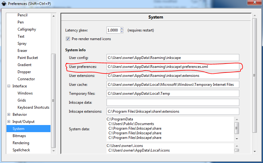
I find it to be a useful practice to take a copy of this file in to preferences-install.xml, because I regularly do something (probably an accidental key press that sets some hot key) that screws up the operation of Inkscape. In such a case, close Inkscape, copy the saved preferences-install.xml file in to preferences.xml then restart Inkscape and you should be good to go again til the next time. You can also just delete the preferences.xml file and Inkscape when it starts will create a new one with default settings (you then need to make the above grid changes again though, and I am lazy …) The one other thing to note on Inkscape is that it is best for Fritzing to use File->Save as then in the “Save as type” field at the bottom select Plain SVG rather than the default Inscape SVG (which adds a bunch of Inkscape specific xml that Fritzing doesn’t always deal well with.)
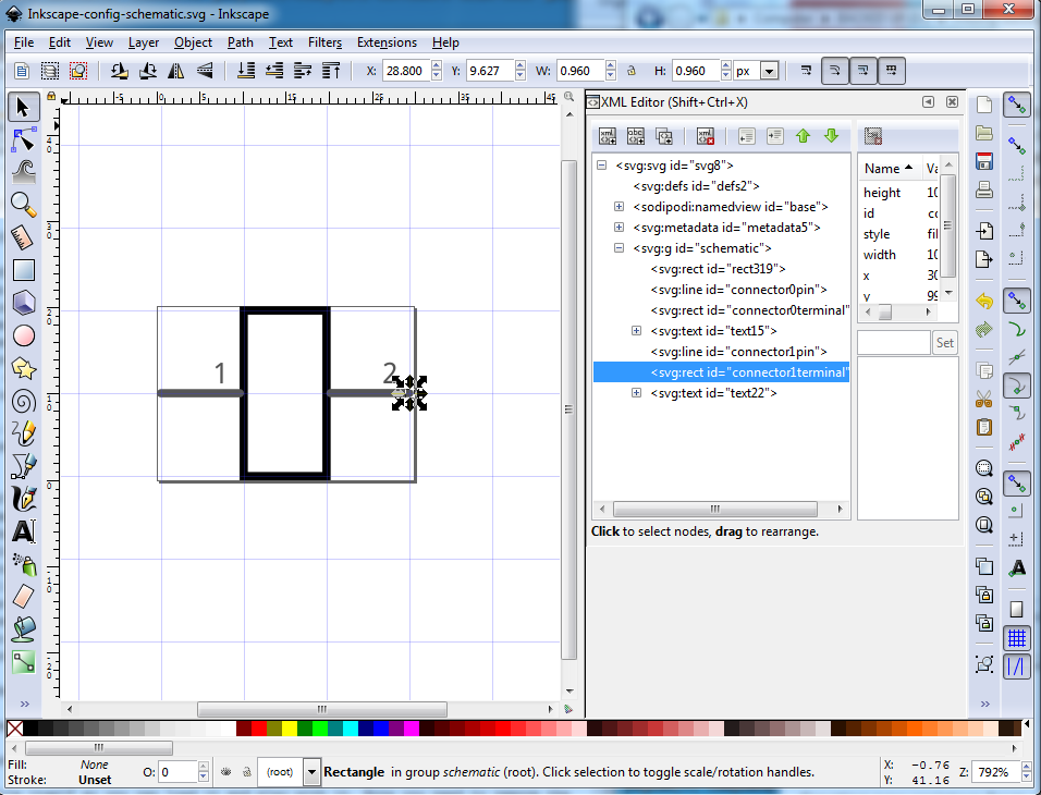
Below is an example of what this gives you in relation to a Fritzing part. This is a simple two pin schematic svg zoomed out, so you see the 10 minor grid lines and how both the pin and the terminalId align to the grid when properly positioned on .1in boundaries. The scale (on the right) is set to 10.41667 as it should be and Units (a bit above that) is set to in. Setting the Units to px is an error, as px has had at least 3 definitions, 72dpi (early Adobe Illustrator), 90dpi (Inkscape 0.92.1 or .2 I think) and 96dpi (Inkscape 0.9.2.3 and later). Fritzing attempts to guess which dpi was in use, and often gets it wrong which results in scaling problems in your part. If you run across an old part that is dimensioned in px, you can (with difficulty!) use the rescaling howto to rescale the drawing appropriately and then save it with Units of either in or mm (which are not subject to guessing about what the dpi was.) Happy part making!

Of note here is the corner of the rectangle. Due to the 0.11in / 0.210in width and height and the fact that the stroke-width of the rectangle is 10 (10 thou in in the real world) the center of the rectangle lines are on the center of the grid. Similarly with the terminalId at height / width 10 (again 10 thou in in the real world) and at x at 0.300 in and y at 0.100in the center of the rectangle (where Fritzing will connect a wire) is at the center of the 10 thou wide line of the terminal so a wire will connect correctly to the terminal in Fritzing. This makes it easy to insure the pins are on 0.1in boundaries as they should be.
the same document except zoomed out til the minor lines disappear, leaving only the .1in grid
and finally the svg file itself so you can load it and play with it. Note you need to remove the trailing .fzp because the forum has trouble with svg files but will accept an svg file called a fzp file just fine (and it turns back in to an svg file when you remove the trailing .fzp).
Inkscape-config-schematic.svg.fzp (2.0 KB)
Examples of how I use Inkscape in making Fritzing parts are available in the two part making documents:
(coming soon I hope!)