Your part likely has scaling issues as the svgs are dimensioned in px,
Warning 19: File
‘svg.schematic.XY-SP5W 5128_1deb0f85b717b891bf3971a5d3e96a74_2_schematic.svg.bak’
At line 3
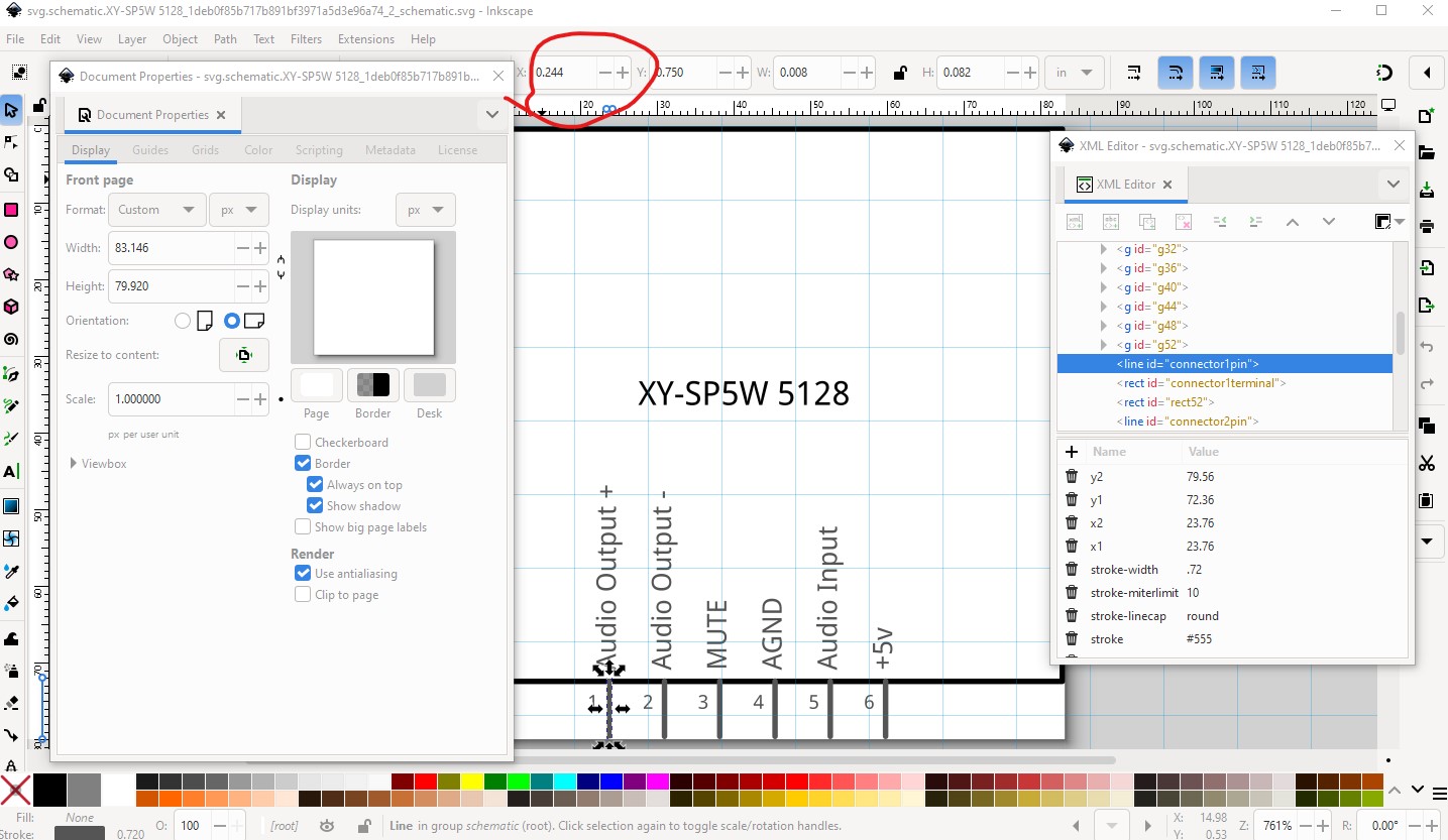
Height 79.92 is defined in px
in or mm is a better option (px can cause scaling problems!)
Warning 19: File
‘svg.schematic.XY-SP5W 5128_1deb0f85b717b891bf3971a5d3e96a74_2_schematic.svg.bak’
At line 3
Width 83.146 is defined in px
in or mm is a better option (px can cause scaling problems!)
Warning 19: File
‘svg.pcb.XY-SP5W 5128_1deb0f85b717b891bf3971a5d3e96a74_2_pcb.svg.bak’
At line 2
Height 34 is defined in px
in or mm is a better option (px can cause scaling problems!)
Warning 19: File
‘svg.pcb.XY-SP5W 5128_1deb0f85b717b891bf3971a5d3e96a74_2_pcb.svg.bak’
At line 2
Width 42.5 is defined in px
in or mm is a better option (px can, and in this case is, cause scaling problems!)
The schematic svg displayed in Inkscape is not on 0.1in boundaries which it should be and is dimensioned in px which should be in or mm.

which causes the pins to not be on 0.1in boundaries which they should be.
and thus causes misalignment in schematic in Fritzing.

FritzingCheckPart.py (which generated the warning messages) and how to fix this is available in this part making tutorial.
Peter