I am sharing a version of the xiao nRF52840 that has male headers soldered.
XIAO nRF52840 with Header .fzpz (126.6 KB)
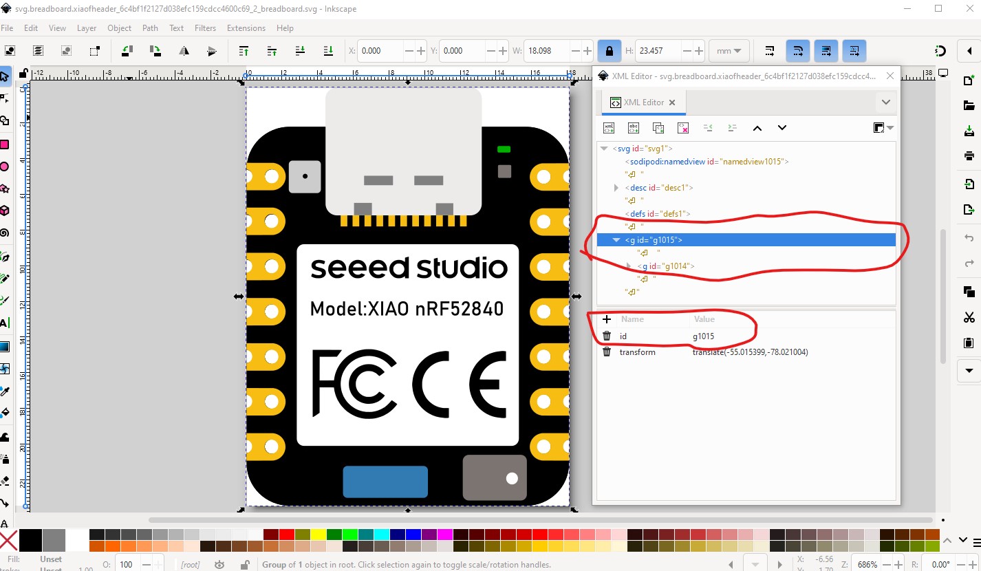
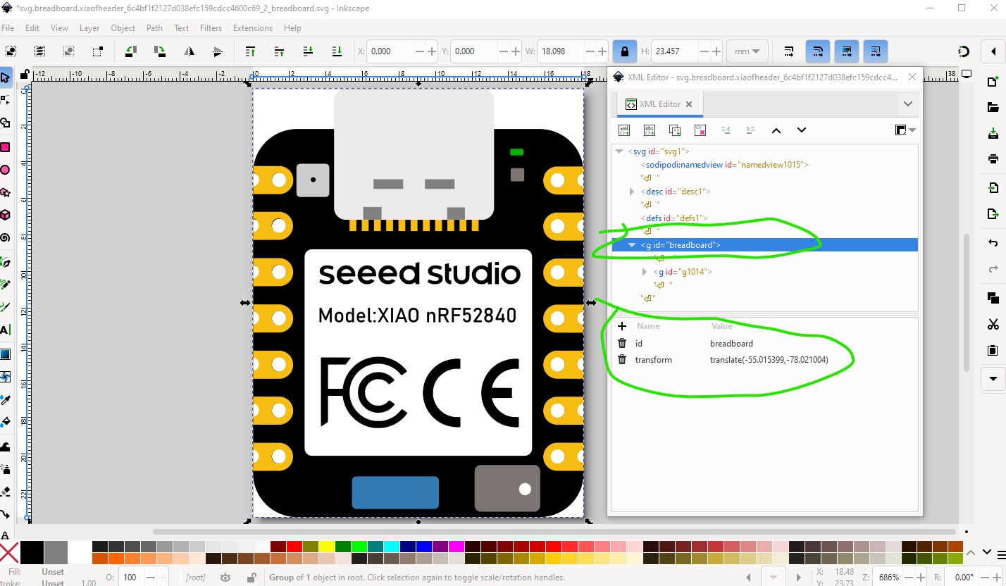
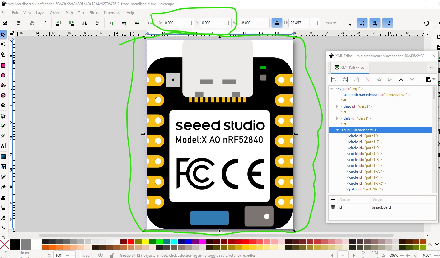
Your part is missing a breadboard layerId which means the part will not export as an image (it will be blank in the exported image.) To correct that you need to name the group “breadbard” like this:
Current:
to this
Peter
Many thanks for the feedback, I will fix this tomorrow.
I renamed the id to “breadboard” and removed some unnecessary groups
XIAO nRF52840 with Header.fzpz (126.0 KB)
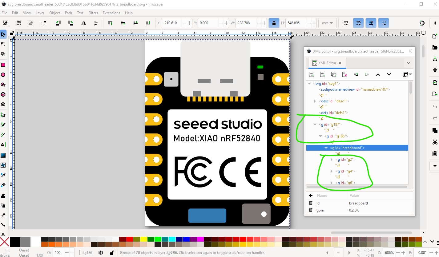
. But in the exported part, the “breadboard” layer is wrapped into two additional new groups. I have no idea why. I tried several strategies to avoid this, but gave up after 2 hours. However, I hope that the wrappers don’t have a bad impact.
It doesn’t appear to and is likely an artifact of parts editor (which loves adding groups.) There is however an issue although it doesn’t appear to be affecting anything. There are a bunch of extra groups (likely from parts editor as noted.) So in Inkscape I selected the top group then hit shift-cntrl-g (ungroup) multiple times to ungroup everything
Then found the start x coord is not 0 which it should be.

Doing Edit–>select all, then Edit→resize page to selection to reorigin it finds the issue

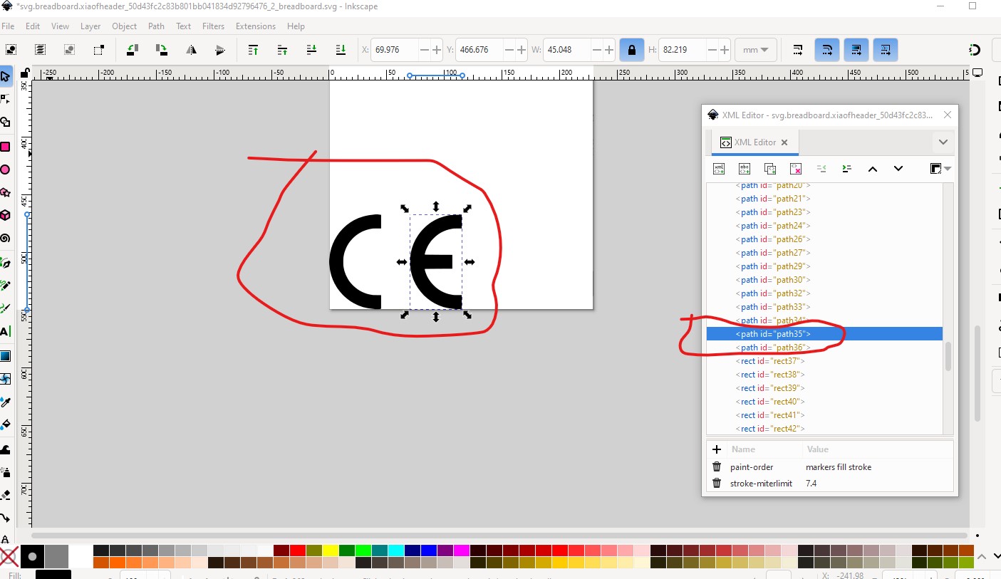
There is an extra CE well out of the viewbox (and thus likely truncated.)

removing them makes the resize work correctly.
Then do a File–>save as and select plain svg (to eliminate all the Inkscape extra crud) and t

Which produces this svg which should be correct and is group free other than the needed breadboard group.
Which is this svg (right click and save image as to down load it!)

This tutorial on parts making covers everything I have done here (as well as FritzingCheckPart.py which I used to discover the lack of a layerId and Randy’s Inkscape extension which would make you a better schematic than the current one.) Hope this helps!
edit:
It would have been useful to include the link to the tutorial!
Peter
Thanks a lot Peter. I will reproduce your fixes and upload a new version soon.
Update: Oh, I didn’t see yesterday night, that you already uploaded the fixed version of the svg. So I just will just pick your version and use it for the part that I am going to upload. Thanks again for your help. Regards, Wolfgang
Here is an updated versiont that has
XIAO nRF52840 with Header.fzpz (107.4 KB)
Peters fix of breadboard view applied.
Looks good, FritzingCheckPart still flags some errors (terminalId in the fzp file but not in the svg) but they will be ignored and not affect anything.
Error 18: File
‘part.xiaofheader_3bb8f37885705d53a8edabcf925e519f_3.fzp.bak’
Connector connector0terminal is in the fzp file but not the svg file. (typo?)
svg svg.breadboard.xiaofheader_962b2c6fbb4e27e8d9bbf671169fb90f_2_breadboard.svg.bak
This is likely an artifact from using a header as the base (which has teminalds in breadboard) but as noted doesn’t cause any issue.
Peter
Since there is nothing that will cause an issue, I will leave it as the final version. I am a beginner in terms of creating fritzing parts and I started learning inkscape just for that purpose. I appreciate your reviews and support to eliminate my errors. Regards, Wolfgang