Name of the part
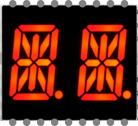
Dual 14-segment alphanumberic display module, Luckylight KWA-541XVB (KWA-541AVB: Common Anode, KWA-541CVB: Common Cathode)
Top view


Datasheet
The official documentation of the part manufacture is linked here:
Model No: KWA-541XVB
Footprint
Custom: I created a KiCAD footprint: DeliveryBox/Circuit/DisplayModule/Displays.pretty/KWA-541XVB.kicad_mod at main · RobertPHeller/DeliveryBox · GitHub if that is helpful.
Type
I did not read this
Breakout board, sub assembly, plug in module (A)
Antenna (AE)
Battery (BT)
Capacitor (C)
Diode (D)
Display (DS)
Fuse (F)
Hardware , mounting screws, etc. (H)
Jack, fixed part of a connector pair, header (J)
Relay (K)
Inductor, Coil, Ferrite bead (L)
Loudspeaker, Buzzer (LS)
Motor (M)
Microphone (MK)
Plug, moveable part of a connector pair (P)
Transistor (Q)
Resistor (R)
Thermistor (RT)
Varistor (RV)
Switch (S)
Transformer (T)
Integrated Circuit (IC)
Crystal, Oscillator (Y)
Zender diode (Z)
Other (please specifiy)
Good morning Robert,
could you please show the sales source here. There are so many listings that look similar.
Is it this part:
https://www.mouser.com/datasheet/2/737/14_segment_alpha_numeric_led_featherwing-1652702.pdf?srsltid=AfmBOooUY27GmQa9BAUPHwUH1QeNnZw6W_mGnYdrJAFFsSmNFltIjImD
Does it look something like this?
Best regards, Harald!
Hi Robert,
it’s me again. I’ve already started working on the part, but unfortunately I can’t find any precise information about the pin assignment.
I only found the following assignment online that matches the image above:
1 - 2 - 3 - 4 - 5 - 6 - 7 - 8 - 9
LED Display
18-17-16-15-14-13-12-11-10
So it starts at the top left and then counts clockwise?
Fritzing would prefer counter-clockwise, but if that’s the pin assignment, then that’s just how it is.
Regards, Harald!
Hi Robert,
I’ve implemented it as described — if you’d like it done differently, feel free to let me know — and of course also if it works!
14_Segmentanzeige_KWA-541AVB.fzpz (8.3 KB)
Best, Harald!
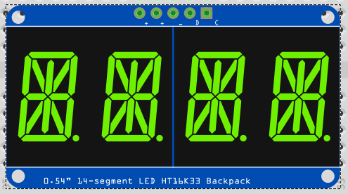
No, this is the Adafruit board (LED "backpack).
No, this is actually wrong. I am looking for the bare displays, not the backpack. The HT16K33 driver chip can handle 8 digits/characters, but Adafruit’s backpacks only have 4 digits/characters. I need an 8 digit/character display. See: DeliveryBox/Circuit/DisplayModule.fzz at main · RobertPHeller/DeliveryBox · GitHub for my crude attempt.
Mouser does not carry the bare Luckylight 14-segment alphanumberic displays, just the Adafruit backpacks, which use the Luckylight 14-segment alphanumberic displays.
No, it is pin 1 at the lower left, with pin 18 at the upper left – counter clockwise. Please see the datasheet, available from Adafruit: https://cdn-shop.adafruit.com/datasheets/CID2379.pdf
(It is not available from Mouser! Only from Adafruit!)
Here is the LuckyLight web page for what appears to be the sucessor(?) part: KA2-541AVB | Luckylight . Its datasheet (direct from LuckyLight): https://www.luckylight.cn/media/component/data-sheet/KA2-541AVB.pdf – it appears to be nearly the same to what Adafruit is selling (the KWA-541AVB) (different segment naming and pin assignments, but it looks like it is pin compatible.)
BTW: The Adafruit backpack quad digit/character display module itself has a fritzing part as part of Adafruit’s fritzing library, as does the ht16k33 breakout board.
I’d like to disagree here — a backpack doesn’t have 18 pins.
But is it correct that two displays are supposed to be visible? That’s what I gather from the datasheet.
The reversed numbering isn’t a problem, but I definitely did not provide you with the LED backpack.
Here’s an image of the LED backpack from the Fritzing library:
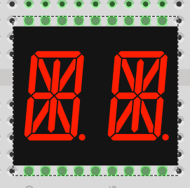
My part looks like this:
Did you import it?
Regards, Harald!
The pins are in the wrong place, with the wrong row spacing. The bare display module pin row spacing is 15.24 mm (.6 in) and the package width (height) is 21.15 mm (.833 in). The package length is 25.1 mm (.989 in). The pins are NOT right at the edge of the package (as is typical for a common DIP type package). The pins are inset – in a top view of the package, the pins are not visible, like they would be with a typical DIP type package. In order to properly place these on a PCB / breadboard, you need to allow for this.
Yes, I imported it. But it is wrong.
Yes, it is two digits/characters – the Adafruit backpack using two display modules to provide a 4 digit/character display module.
Hi Robert,
yes, that’s correct. But you’re talking about the breadboard view. For the PCB, the PCB view is what matters — that is, the footprint. In that view, 15.24 mm is correct, just as stated in the datasheet. For the breadboard view, however, the pins need to be visible (I think) — they shouldn’t be covered by another layer, such as the enclosure.
Here’s what I suggest changing:
- Change the pin order: PIN 1 at the bottom left and PIN 18 at the top left, in all three views
- Change the pin spacing in the breadboard view to 15.24 mm
- Adjust the enclosure width to 15 mm (this isn’t relevant for PCB manufacturing though — that’s what the PCB view is for).
If you’re okay with that, please let me know.
In the meantime, I’ll test a breadboard view where the pins are underneath the enclosure — I’m just not sure yet whether that will work.
Best, Harald!
It does work. I’ve done it on other parts. It matters because sometimes the pins on the breadboard might not be able to align with the “fake” (visible) pins, but are fine with the real pins.
I didn’t check with the PCB view, since I never use fritzing to design PCBs – I use KiCAD for that.
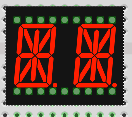
…yes, I just tried it as well. It would look like this:
Should I go ahead and implement the suggested changes like that?
Best, Harald!
…I’ll get to work tomorrow morning and adjust the thing.
Best, Harald!
Good morning,
I hope I’ve fixed all the errors now. I’ve also attached an example sketch. The part now has a different ID, but that doesn’t matter. To import it, you’ll need to remove the old part from the library first anyway.
Part:
14_Segmentanzeige_KWA-541XVB.fzpz (9.4 KB)
Example:
Test_Sketch.fzz (17.3 KB)
I also went ahead and ran the Fritzing test script on it. It didn’t find any technical errors. So now there can only be logical errors.
Best regards, Harald!
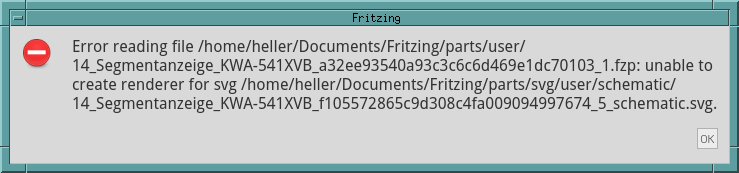
I imported the file, but I am unable to actualy use the part. I am getting this popup:
I am using fritzing 0.9.6 (b) 32 ]Qt 5.15.6] on a RPi 5 running Raspbian 12. This is the version of fritzing from the Debian repo for Debian 12 (bookworm).
There seems to be no schematic image and when I tried to edit the part, fritzing segfaulted.
That’s weird, let me take another look at the file…