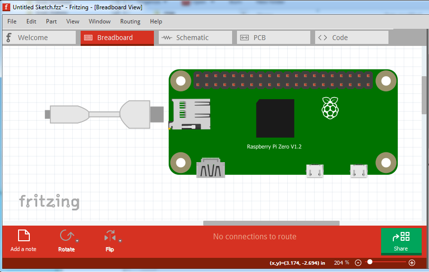
Does someone know where to find the usb cable parts shown in this breadboard view:
Image source is found here in the Raspberry Pi forum.
Does someone know where to find the usb cable parts shown in this breadboard view:
Image source is found here in the Raspberry Pi forum.
Nice, thank you Peter.
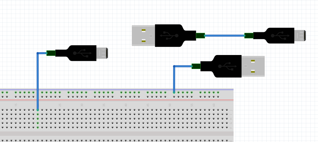
@vanepp I have added some more detail to the usb plugs in the breadboard view.
Micro_USB_B_Plug.fzpz (12.0 KB) USB_A_Plug.fzpz (9.9 KB)
@vanepp do you have some suggestions what to do with the schematic and pcb views?
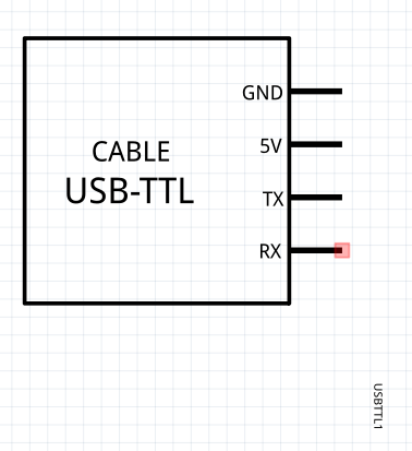
I don’t know what to do with the RX, TX, 5V and GND pins in these views as they are not directly exposed in the breadboard view. Would you suggest to disable the schematic and pcb views? If so, how can I disable the schematic and pcb view in fritzing?
Yes, copy the layer configuration in the .fzp file from my original part. That suppresses schematic and pcb view. You will need to edit the fzp file directly as parts editor can’t do this.
edit:
Here is a modified version of the USB A plug with schematic and pcb suppressed.
USB_A_Plug-suppressed.fzpz (3.9 KB)
Peter
I maybe bumping on years old post,sorry.
How do we find USB B type fritzing part, I wanted to conduct bi-directional serial communication for Arduino Mega 2560 and Rasp Pi 4B, because raspberry pi has USB A type and Mega got USB B type.
Thank you.
Will this do? I’m assuming you want a part for a board rather than the A to B cable (which can be created with the parts above and a wire, although they won’t connect in schematic to either the mega or PI 4b as neither of them have connectors on the USB port.) Otherwise a data sheet for the socket you want would be needed to make a custom part.
edit forgot the post!
edit1
There are also connectors in core parts. Enter
usb B connector
in the search box to bring them up.
Peter
You should be able to connect USB to Arduino or Mega even though there is no connector for it. My understanding is that effectively the 4 wires for usb connect to ground, 5V, RX and TX (for main serial)
I don’t think that is correct. I believe the USB connector goes in to a USB to serial chip on board and the serial output from that chip goes to rx and tx. The USB connection isn’t serial (at least in the RS232 sense, it is in some sense serial at around 400mhz, just not async.)
Peter
That is why I said “effectively”. If you want to model accurately, you would need to put the usb/serial chip in between. But as far as voltages and signals paths go, it is accurate.