Is there a part for fritzing have spent hours looking but no luck as yet. still a noob so i do apologise if ive missed something obvious.
Seeing that it is such a new connector I doubt one already exists publicly. Are you making a PCB or using it to document things in the breadboard view? If you are making a PCB and there is a specific part you are looking for can you provide a link to a datsheet so we know what you are looking for. Everyone is slightly different when making a PCB. Some have two tabs, some have four. Some are normal and some are mounted at 90 degrees to the board. Some have locator pins and some don’t etc.
1 Like
Thanks for your reply, i’m making a pcb, already had one printed with aisler that arrived today but want to advance it to include the USB C. The datasheet link is here https://uk.rs-online.com/web/p/type-c-usb-connectors/9209199/
thanks for any help
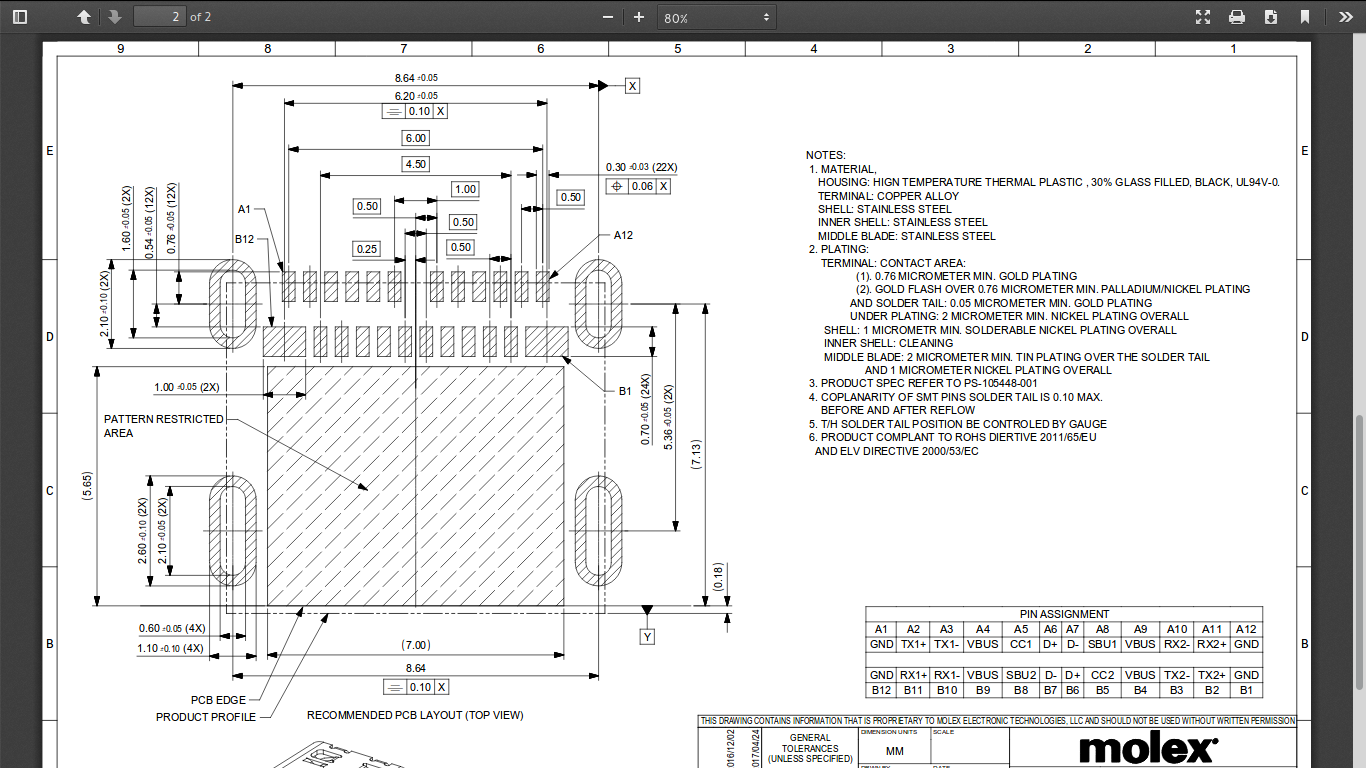
Thanks for the link. After a bit of searching I found the foot print in this document http://www.molex.com/pdm_docs/sd/1054500101_sd.pdf
I personally do not have the time right this second to make the part. If I do find time before someone else does I will see about making it. If you are in a hurry and no one volunteers to make it you could dive into making parts. There is a learning curve that stops many people and unfortunately the instructions around the web are conflicting at best because the process of making parts has changed since Fritzing was first created. If you do go down the parts creation rabbit hole feel free to ask questions here on the forum, there are many people around that do know how to make parts that are willing to give advice.
Thanks, I will give it a go. Seen parts created in SVG files before is this the best way to do these or is there a specific program you would recommend maybe one you use personally, that diagram helped. Thanks again.
Just read in forum, Inkscape. Have that, here’s hoping. 
I also use Inkscape as I am a Linux user and it is the best Opensource vector graphics program available.
This is the tutorial I had saved in my bookmarks so I think it is the one I found most useful https://learn.sparkfun.com/tutorials/make-your-own-fritzing-parts .
1 Like
I can make a foot print for this easiliy enough except for the mounting tabs which appear to need an oval slot with a copper surround. I’m not sure the gerber output supports slots (but I also don’t know much about the gerber code either). If someone can tell me how to code the slot (if that is indeed possible) I can do this easily enough.
Peter
I’ve not used inkscape before so still trying to get a grip on it, but that would help. I’m wondering maybe would it be possible to edit say a micro b usb from adafruit that has similar tabs?? or do you need to build a whole new part.
I just did some research and from the looks of it Fritzing does not have a way of making slotted holes for connectors. You could use a larger hole the diameter of the longest dimension, multiple overlapping holes (most board shops won’t make this) or draw them in the actual board layer but then they are not plated. The last option would be to find a different connector maybe one with smd tabs not tht tabs or maybe one where the hole are further from the connections making it easier to use round holes.
I’m going to see if @steelgoose 's odd shaped board holes will work for this. In theory it may (I don’t think the mounting holes need plating). As you say the pads are to close to allow a hole to be used for the tabs.
Edit: Nope, doesn’t look like it will work. Over and above that the slots didn’t make it, the pads are misscaled (perhaps because they are too small) in the gerbers. Maybe someone else can figure out a fix.
USB_3.1_typeC_usb_connector.fzpz (9.7 KB)
Peter
1 Like
If I had these connectors already and was trying to make a board I would bend the tabs out and make the footprint an smd pad like the micro usb ones.
Micro usb footprint

1 Like
just an idea but if the part cant work because of the mounts, would it be possible to do something like this. as the part will still fit to the mount and overlap the connector (basically square off the ports, overlapped the old mount over suggested new one on pic) ?
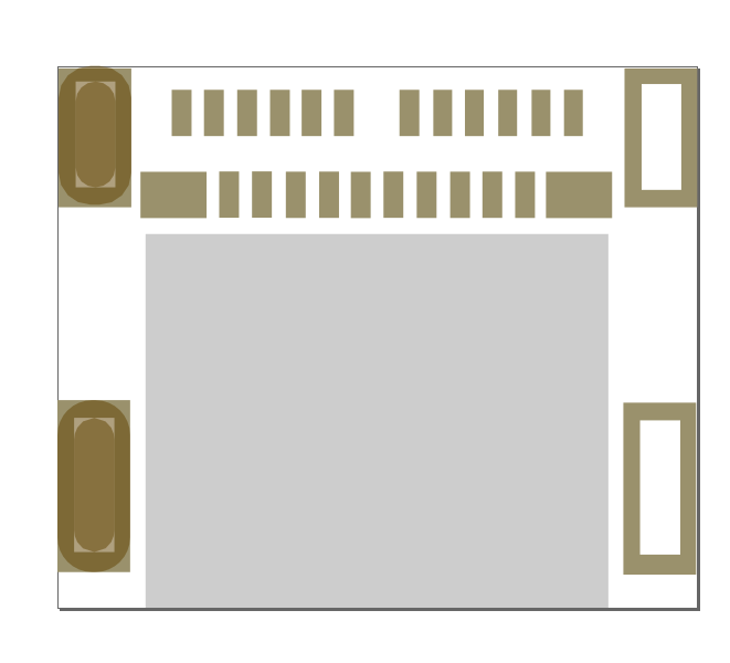
new to this so heres hoping… plus dont know if i’ve built the svg correctly, as no defined copper layers lol still learning.
after re-reading , are you saying its not possible to add any slots?
@customerx, @sublimeartistry, @vanepp
Well, you are right in all cases; You can’t overlap drill holes “it would probably snap the drill bits”. I just use a round hole when possible, but not always possible. I have seen boards with these slots but I don’'t think they were made by a 0.6mm router bit. I believe these slots are laser drilled… most modern pcb machines have laser drills for the very small holes. But there is no way to draw them up in Fz or tell the fab house how to cut them. The tabs really need to be there to help line up the part for the smt solder pads and the part gets a lot of stress.
My suggestion would be, is to drill a hole at each end of the slot and as many holes in-between on the longer slots leaving a space in-between the holes so the holes don’t touch each other. Then take an x-acto knife and cuts the tabs out making it a slot. I believe the copper is just so the housing will be grounded and the solder will take care of that when you solder the tabs in.
1 Like
it looks like using a dif program, or learning quite some more before what I want is going to be achieved this way, appreciate all your hard work guys.