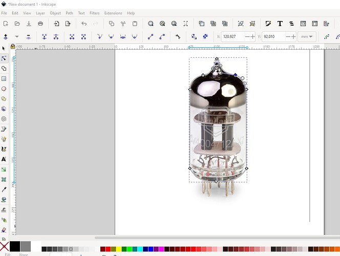
It gets easier once you get used to your svg editor. This series is in Inkscape which is both open source and thus free (and popular) and has good control. Illustrator as far as I can see from their documentation doesn’t allow anywhere near as much control. Here I started from a jpg image of a tube (looks to be 7 pins)
Then created a path with the path editor to outline the tube and set a stroke (relatively small) to set the outline then set the fill color from none (the image above) to a light white which blocks the image of the tube:
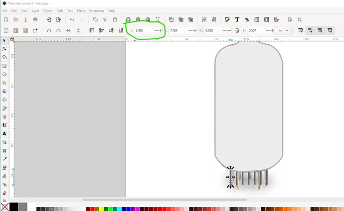
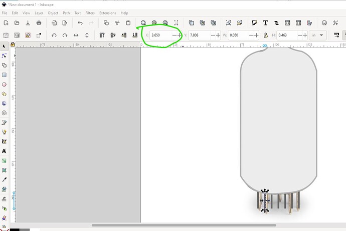
The pins are rectangles (a line would be a better bet but I don’t have one handy and Inkscape won’t create them but can deal with them for Illustrator!) Spacing is fairly easy here I set the x coord to something standard and then duplicated the pin and used the tool bar to move it in x by 0…2in
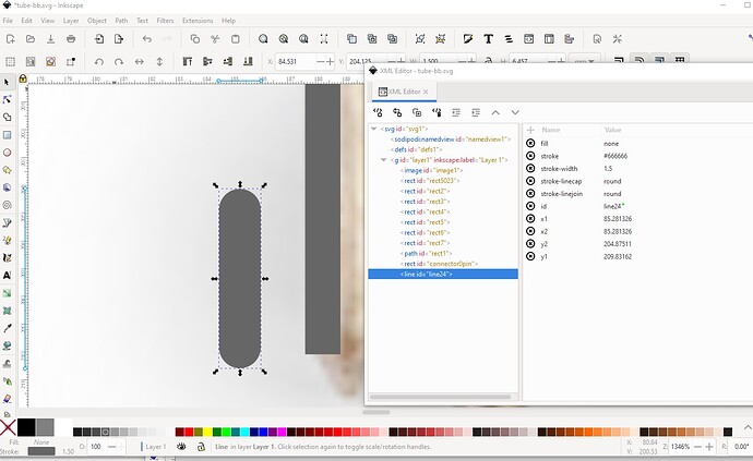
Rinse and repeat for the other 5 pins and we are done. Technically I should also add the internal tube stuff, but that is optional and I am lazy ![]() . I would need to add some no stroke no fill rectangles to the bottom of the pin to make the connector pads connect to the bottom of the pin (and use a line with like this):
. I would need to add some no stroke no fill rectangles to the bottom of the pin to make the connector pads connect to the bottom of the pin (and use a line with like this):
all of that is in this svg (including the image I made this from)
if you right click on the svg and select Save image as you can download the svg to look over and use if you wish. There is more information on parts making in general available in this tutorial as well
and I am always willing to help people make parts (it is however difficult!) although you look like you are well on your way now.
Peter


