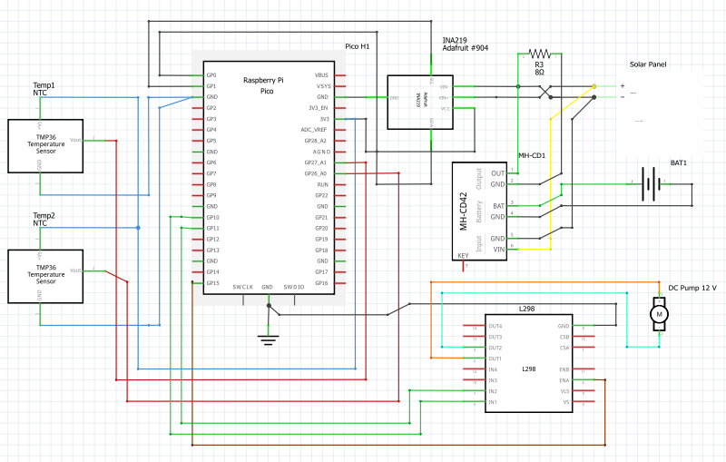
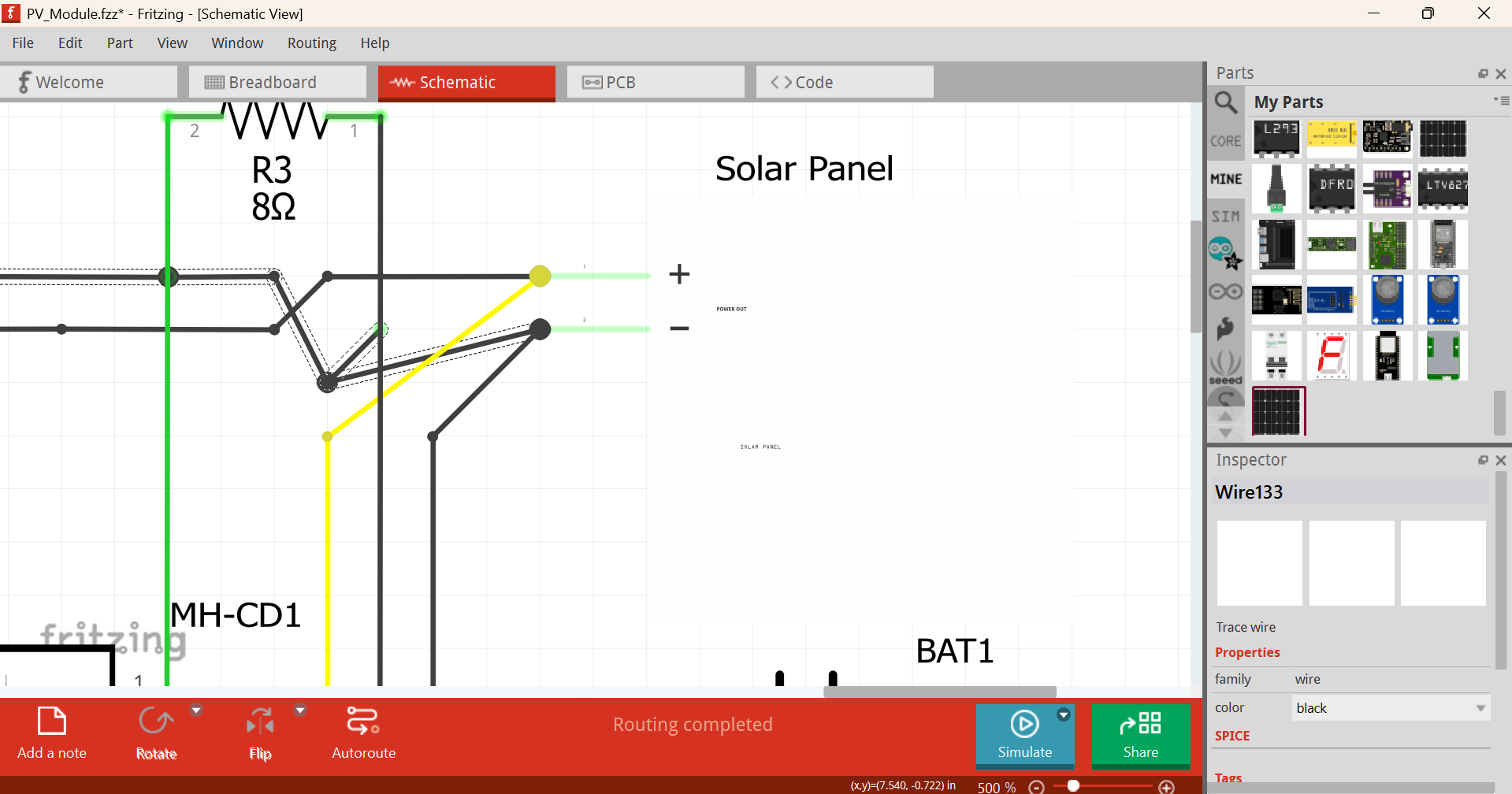
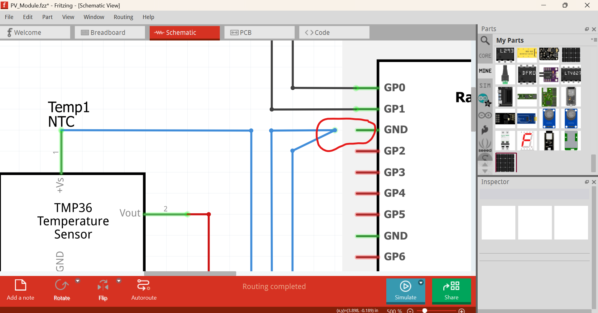
Hello everyone! new to fritzing and i needed some help, do you think my schematic is good? the breadpoard is a mess but im more interested in the schematic. To sum up my project, Im studying the effiiciency of solar panels ( 50 W panel) using liquid cooling. The 2 temperature sensors are mounted one on the front and one on the back, im using the INA219 to measure the current+voltage.
The way i want it to work is:
Charge the 12V battery to full using the battery charger
Use all the battery on the 50 W 8 Ohms resistor to dissipate the energy.
Measure the efficiency of the solar panel while the battery is charging.
(The DC Pump is going to circulate water trough a copper pipe on the back of the PV panel and i will try 4 different speeds to measure the impact.)
I want to also do another study: directly disspate the energy from the output of the resistor, meaning the battery is not charging and the pump and the resistor is directly connected to the pv panel.
Im aware the PV panel is relativley small so the impact of temperature is not that high but im sure i should be able to measure a significant difference.
Next where did you get MH-CD part from? It’s fairly broken. Also, Adafruit parts generally (unless fixed by me, Peter and a few others) have (not-so-)broken schematics, thanks to old Eagle2Fritzing
The MH-CD42 unit is intended for use with 3.7 Volt LiPo cells not a 12V battery so that is likely not going to work. As well 8 ohms across a 12V battery is going to try and draw 1.5A which is likely far more than the MH-CD42 is designed for (although I am not familiar with the specs of the MH-CD42.) There are a couple of other solar controllers available as Fritzing parts one of which may be more suitable. A google search of the form “fritzing part solar controller” should find them. One of them may deal with 12V batteries. As to the schematic, you should rotate the various parts to improve readability and rearrange the parts to make the wires shorter (which also improves readability. The L298 motor controller likely needs a source of 12V to power the pump which is not shown (I assume that isn’t the 12V battery as the current draw of the pump would affect the current measurements of the test battery.) As well the Raspberry PI needs a power source somewhere (that may be a wall ward or USB connection though.)
From the original description, you might want to also track ambient temperature and light level. Efficiency is based on incident light. Details like whether the panel is tracking the sun or not. A ‘simple’ LDR (light dependant resistor) would be a start, but probably not enough. It is not likely to match the response of the panel. Panels are more efficient at specific frequencies (colors). You really want 2 ‘matched’ panels, one cooled, the other not.
I plan on connecting the pi pico to my computer to track the Voltage Current and Temperature, maybe make a simple excel that can represent the data im gathering.
That is an amzing idea! I think I will make the first test without the cooling radiator and the second one with cooling. I cant afford 2 panels as they are very expensive here and my buget is quite limited
I actually couln`t find the XH-M600 module that can charge my 12 V battery, I just looked for a decent alternative, went for the closest thing. I wanted to charge the battery then use it for the L298 and the pump. Like use the panel to charge the battery, then drain the battery by using it for the motor, or maybe I will follow your advice and get a separate 12 V battery for the motor.
There is a part here, but the company looks to have gone under their web site no longer resolves.
a google search for “12V solar controller” turns up a bunch of hits with various amperages and prices. If you pick one I can make a part for it easily enough (if the listed part doesn’t already have the connections needed!) You likely need one designed for 12V I expect, a LiPo one likely won’t work.
Using a single panel avoids the problem of needing a matched pair. Doing at other times introduces a different variable though. The ‘test’ conditions could be different at different times. It makes it more important to also track ambient conditions during each ‘test run’. I think you need more than a first and second test. My initial guess is that alternating cooling and no cooling each day for as long as you can afford will get the best data. That should help filter out effect of slightly sunnier or slightly warmer days.
If you can setup for ‘simulated’ sunlight, and are able to control the conditions yourself, it would simplify the analysis.
Not bad, for someone new to fritzing. I think you could make better use of NET Labels, though, as that takes away the complexity of having to route wires all the way round each component. Of course, for smaller circuits like this, it’s fine.
Overall, I’d give your schem drawing a solid 7.2/10! Way more than I could achieve when I was a Fritzing beginner.