I created a new file today in breadboard view. When I exported it to svg some parts are missing.
The missing parts are builtin parts Arduino Nano and microsd.
The wires and other parts appear in the export but these two parts are missing.
I created a new file today in breadboard view. When I exported it to svg some parts are missing.
The missing parts are builtin parts Arduino Nano and microsd.
The wires and other parts appear in the export but these two parts are missing.
This issue appears to be only in the svg export. I tried exporting as pdf and the parts appear.
However there is no way I can edit a pdf, I can edit an svg
Can you post the sketch file here? I have seen similar problems before caused by various things, with work-arounds that work in some cases. Sometimes it is caused by an error in the parts. Builtin parts are not immune to bugs. Sometimes it is a Frtizing export bug, but tweaking the part svg can work around it.
You can also export in bitmap image format (png and jpg). Those are editable, but of course not in the same way that svg is. The pdf is actually just a wrapper around a bitmap image.
I can’t find a way to attach the fritzing file so here is a link to the file on Fritzing file on My Dropbox
I’ve got the file from Dropbox now, but for future reference, a file (of supported types) is attached here using the “Upload” button at the top of the text edit window when creating a post or comment. 7th icon from the left. Looks like a bar with an arrow point upward. You can also just drag and drop a file in the edit window.
Oh wow. I didn’t notice that. Thanks for the tip on uploading
I ran the sketch through some preliminary tests. I can confirm that I get the same symptom you described using version 0.9.4. With a development 0.9.5 version, it is even worse. A third part got dropped. I also created a test sketch with just the nano board, and that failed too. I suspect the real cause is a bug in the svg file processing/export, but digging deeper to see if a minor change to the breadboard svg image will avoid the problem. I’ll report back on what I discover.
Thanks for the update and the help. I look forward to hearing from you
I have another circuit diagram where a part disappears on svg export.
The part that disappears is the accelerometer/gyro module
I am attaching the fzz file
Accelerometer and Display.fzz (29.8 KB)
Turns out that the code is not the real problem. There are errors in the part files. Or if there is a code error, it is that Fritzing is being too forgiving of errors in the part definitions when displaying them in the view.
The “Airplane Data Logger.fzz” sketch is using the core “Arduino Nano (3.0)” part, and a customized (with pin labels) copy of the core “microsdmodule” part for chip PG6SD. The nano part has an error in the breadboard view layer names. The definition says the layer is “breadboard”, but the svg files contains “breadboardbreadboard”. The breadboard svg image for the core microsdmodule part is completely missing the wrapper element for the breadboard layer. The customized copy does not have that layer name either.
In each case, Fritzing displays the complete image content in the breadboard view, but does not export it to svg. The svg export actually looks at the layer name, and only exports graphical content that matches the layerId specified for the part. As is, there is no content that matches for these parts.
The (manual) fixes are simple.
Change “breadboardbreadboard” to “breadboard” in the part library image file …/fritzing-parts/svg/core/breadboard/Arduino Nano3_breadboard.svg
Add <g id="breadboard"> before the first graphical element in …/fritzing-parts/svg/core/breadboard/microsdmodule.svg, and add </g> just before the closing </svg>. Same fix for the custom part breadboard svg.
The accelerometer/gyro module is another custom part. From a quick look I can not tell where the breadboard view graphics file came from, but it also is missing the wrapper group to specify the breadboard layer. Same fix. Either add the open and close group entries manually with a text editor, or select all content in an image editor (like Inkscape), and inserted it in a new group with an id of “breadboard”.
There are other core parts with similar problems. Nobody seems to have noticed (or at least complained). I expect, because most are doing exports in the bit-map formats, that do not have the issue. Those effectively take a snapshot of the graphical view, and since that is showing the image content even though it is not inside the layer, everything looks good. I’ll see about detecting more of the problems parts, and getting a library update for them.
For custom parts, the FritzingCheckPart tool will report Found a drawing element before a layerId (or no layerId). It reports the same for core parts, but the sheer volume of what it reports has been hiding these cases. That, and there is a (half-way) planned project to go through and cleanup a lot of different errors in the core library parts. It would be nice to be able to do all of the fixes needed for a single part at once. Probably better/easier, for some errors, to fix all of a specific type of error as a group.
FritzingCheckPart is reporting additional issues with the MPU-6050 part, that might cause problems for other cases.
The px warnings are the most important from that. It also looks like the part was never “finished”. The schematic view is for a pin header, instead of SPI/I2C part. Which also shows in the part family and other properties.
That is a lot of work. Thanks
I made the changes to the nano and microsd module and it still will not export the parts in svg. As far as I could tell I changed the correct files.
I am not sure where I downloaded the MPU-6050part from.
Is the FritzingCheckPart something that I can run or is it part of the program itself?
For now I downloaded jpg images of the nano and the microsd module then inserted them into the svg where the part was missing.
I only have two sketch diagrams so this will work for now. Although I have 2-3 other projects I am working on that will need diagrams when they are completed.
Thanks I appreciate all the effort
I believe you are running on windows, so the file for the nano should be:
c:\Users\username\My Documents\fritzing-parts\svg\core\breadboard\Arduino Nano3_breadboard.svg
That just needs “breadboardbreadboard” changed to “breadboard”. Then restart Frtizing and reopen the sketch file. The microsdmodule is bad in core as well, but fixing it will not fix the sketch, unless you replace the custom part with the one from core. The ‘official’ way to fix that (part), would be to load a fixed copy of the svg in parts editor, save it, then update the sketch to the new version. You could short cut the parts edit by editing the svg directly, probably:
c:\Users\username\My Documents\Fritzing\svg\user\breadboard\prefix0001_9ca6bc4aa047adc880b0dc372f469a8d_1_breadboard.svg
based on the image file name used in the sketch. The core part should update in the sketch when the file is opened. Still have to delete and replace the custom part in the sketch for it to get the new version. Use “Delete minus”, to keep all of the wires, drag the updated version into place, then grab the end of each wire (move and move back) to get them to reconnect.
There is a similar workaround to update the custom part directly in the sketch. Unzip the fzz to a folder someplace, edit the bad svg file, zip it back up again. Don’t rename while zipping up. The internal .fz file is really the sketch name, and should match the .fzz.
FritzingCheckPart is a separate tool. Using python. It has its own home on github.
That tool is underdevelopment as well. Sometimes you need to decide if what it reports is really a problem or not. But it catches a lot of simply typing errors and mismatch between file in a part.
You are correct, I am using windows.
The parts location is a little different. I did not extract the fritzing app to the programs folder since it did not have an install. So for now I just put it on the desktop.
The location of the parts is (name changed to … for privacy)
C:\Users…\Documents\Fritzing\parts\svg\user\breadboard\prefix0001_9ca6bc4aa047adc880b0dc372f469a8d_1_breadboard.svg
C:\Users…\Desktop\fritzing.0.9.4.64.pc\fritzing-parts\svg\core\breadboard\Arduino Nano3_breadboard.svg
This fixed the Nano export. But the sdmodule, accelerometer, and oled display still do not export.
The lack of the correct layerId is the only thing I am aware of that causes svg export of the part to fail, but there may be others as well. Best bet would be to upload the .fzz file here. That will have the parts files for any part not in core in the temp parts bin and one or another of us can have a look at it and tell you what is likely going wrong. The most likely cause is that the layerId in the.fzp file doesn’t match the layerId in the svg file (the case must be the same on Linux and Mac, as well, as they are case sensitive unlike Windows.) If you unzip the .fzpz file for the part (I use 7zip) you will get a .fzp file (which is xml) and 4 svg files. The layerId is specified in the .fzp file and need to match the group that encompasses the entire part in the various svg files. You can use a text editor to ensure that and then just rezip the 5 files and change the extension to .fzpz to remake the part.
Peter
@vanepp The problem fzz files are in in earlier comments. That is what I already used to report the exact problems. One was a bad id value in the svg, the other 2 were totally missing breadboard layers ids. both core parts and custom.
I have same problem with another component, could you help me to find how to solve it?
Stromversorgung Breadboard.fzpz (14.6 KB)
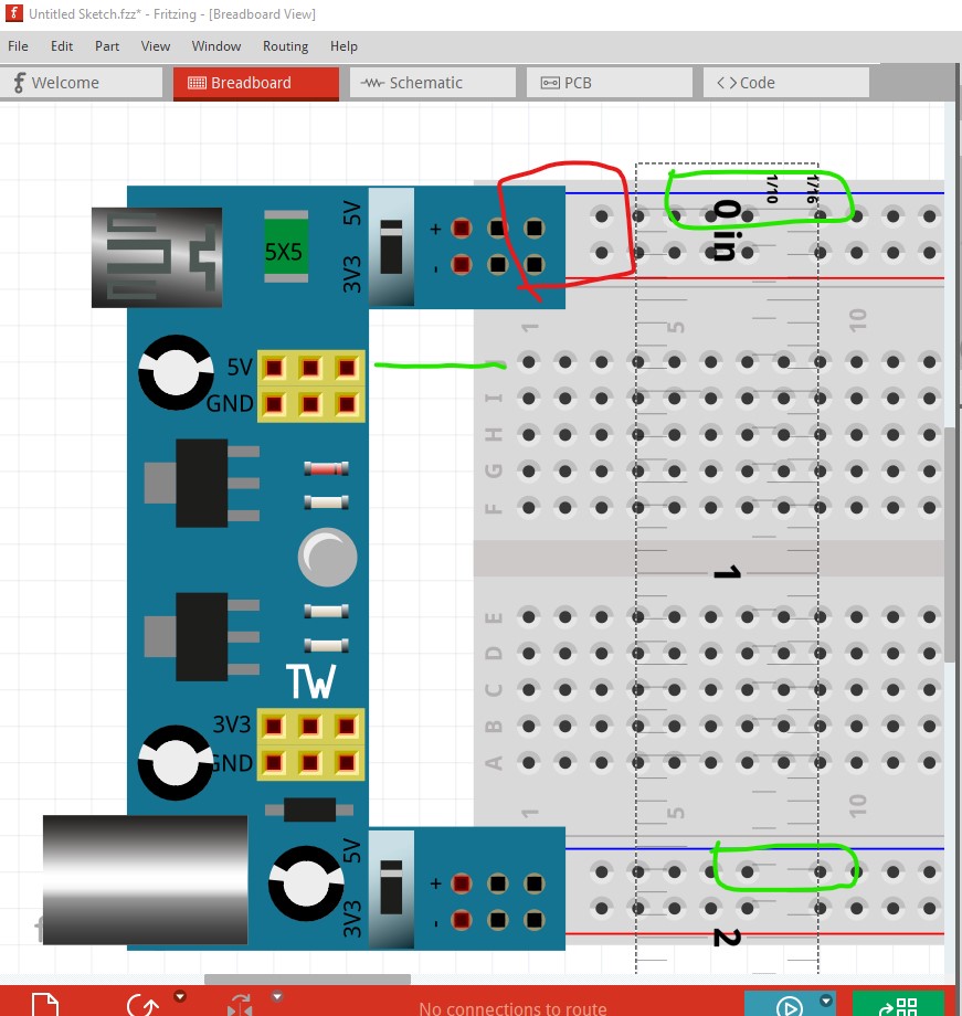
the component dissapear when it is exported as svg format
There are more than a few issues here, but I have corrected most of them. Breadboard is slightly misaligned (corrected now) The yellow connector needs to move down in Y slightly to line up on 0.1in boundaries. It connects to the breadboard correctly anyway but aligned is more desirable.
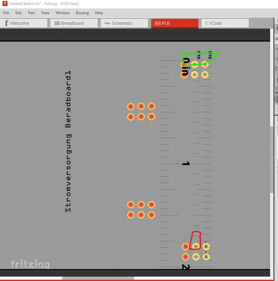
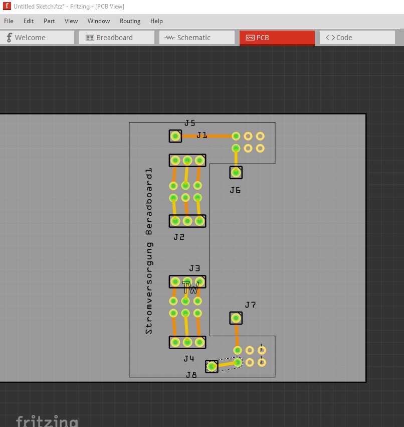
Pcb appears to be wrongly spaced (I didn’t correct it as I assume you aren’t using it.)
Here in breadboard we see the space between the top and bottom power pads should be on a 0.1in boundary and breadboard appears correct. However in pcb the pads are not aligned on a 0.1in boundary which they should be to actually fit in a breadboard. As noted I didn’t fix this.
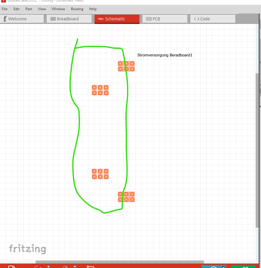
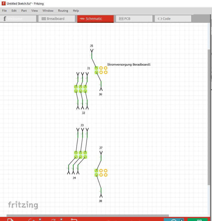
schematic looks correct enough, but should normally be a schematic not a copy of pcb. Again I didn’t correct this as I don’t know if you are using schematic or not.
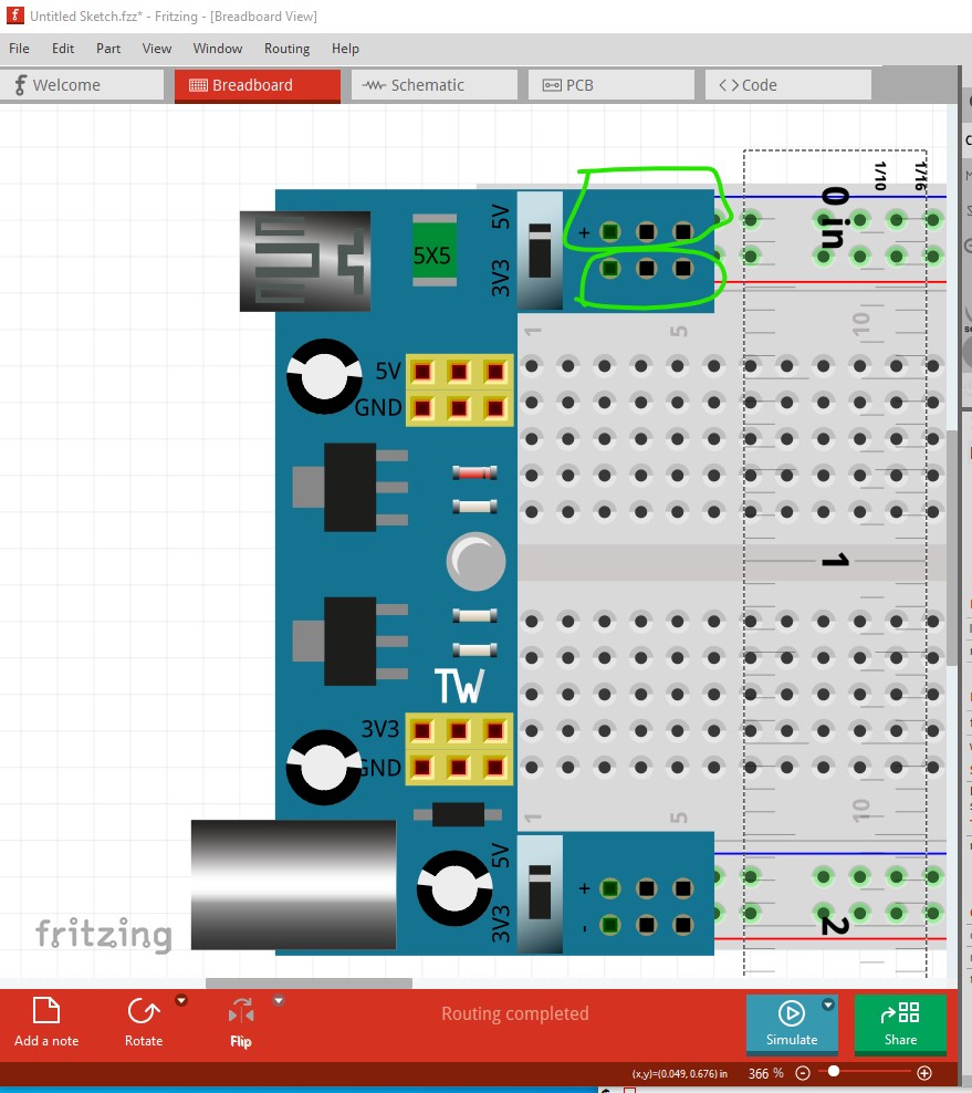
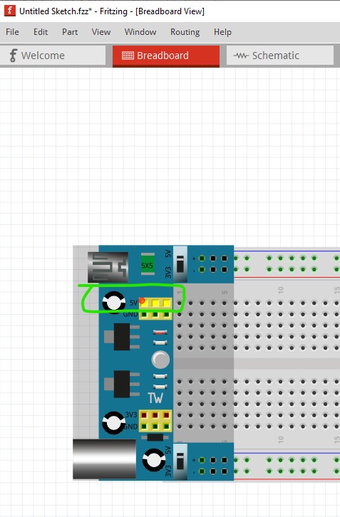
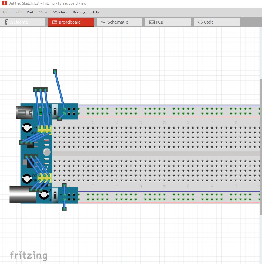
This is the change in breadboard. The two yellow connectors got moved down a bit to be on a 0.1in boundary.
groups got added to the fzp file so now right clicking on any ground pin will light all the ground connections yellow like this.
same with the 5V connections
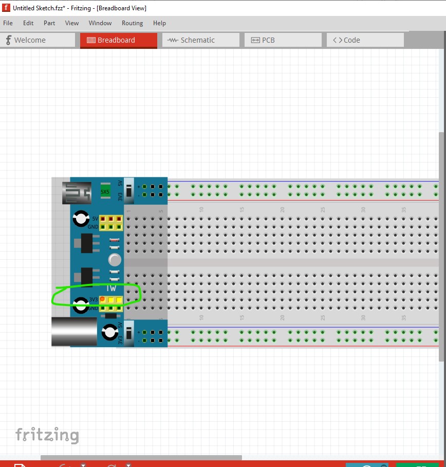
and the 3V3 connections
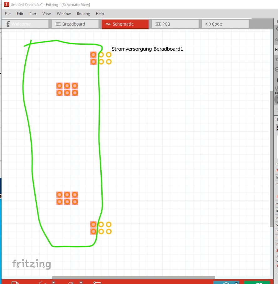
the new schematic (as well as having a correct layerId so it will export as an image) now shows the active connections that wires will connect to.
The 5V and 3V3 and associated grounds will no longer connect to the breadboard (and thus won’t short via the breadboard as the original was. This has connections to all the active pins
which then reflect in to schematic
and pcb
although as noted I don’t think the spacing on pcb is correct. All of these changes are in this part:
Stromversorgung Breadboard-fixed.fzpz (15.4 KB)
since I didn’t change the moduleId of the part, to load the new one you will need to delete the current part from your mine parts bin by right clicking on it and then clicking on remove part, then shut down Fritzing answering yes to save the new parts and the changes to the parts bin (you can say no to save the sketch though.) When you restart Fritzing the part will be removed and the new part should then load in to the mine parts bin.
Peter
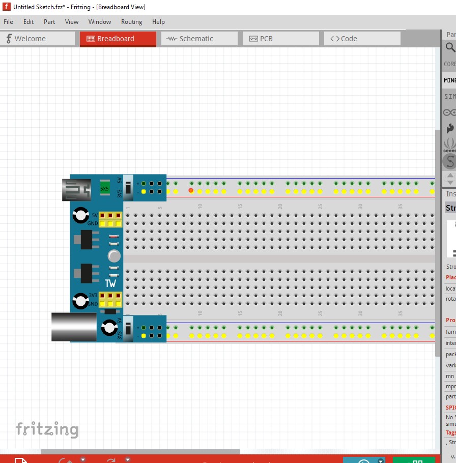
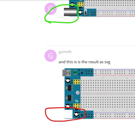
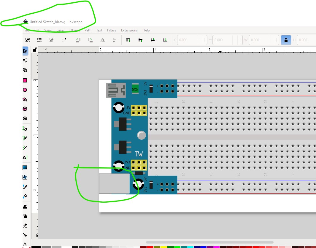
I’ve tested your new file
this is in the software
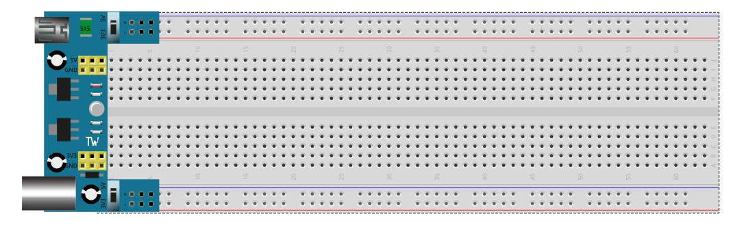
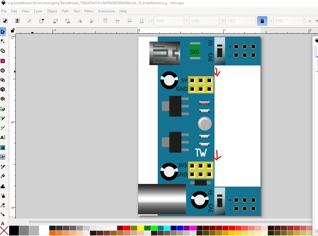
and this is is the result as svg

why is happening this?
I expect the problem is linear gradients. The barrel of the connector is a linear gradient (which Fritzing didn’t used to support) I would guess that it is now able to be rendered by Fritzing but can’t be exported as an image. I can remove the linear gradient in breadboard and that should fix the issue but it will look a little less good I expect.
edit
With the linear gradient removed the svg looks like this:
pretty much what the svg export looks like. I can replace the linear gradient with a rectangle like this
which doesn’t look as good but at least should export correctly. It would be a good bet to open an issue on github in case this is a bug that can be fixed as well. Here is a new part with the linear gradient replaced by a rectangle which does export as an svg and may do you.
which came from this part (again you will need to delete the current part to load this one)
Stromversorgung Breadboard-fixed.fzpz (14.2 KB)
Hope this helps
Peter