Suggestions for additional documentation

Even better, but likely more code work, would be to have an optional attribute in the fzp file property attributes to make it editable in Inspector. As a base

<property name="voltage" editable="true"></property>

Extend that with the attributes currently used in the properties.xml file. Extend that again with an attribute to pull in a template from properties.xml (or elsewhere)

<property name="voltage" editable="true" rule="voltage" />
<property name="voltage" editable="true" choose="3.3,5" />
<property name="gain" editable="true" pattern="\d{1,4}(\.\d{1,3})?" />

The last (supposed to be) a regex pattern for a number that is either a number the is either an integer (up to 9999), or floating point value with up to 3 digits after the decimal point.

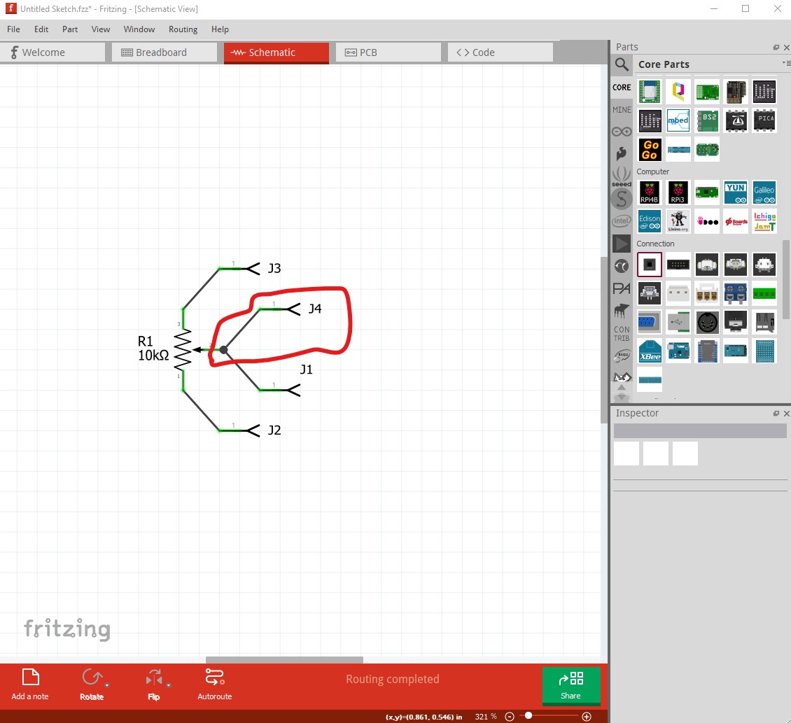
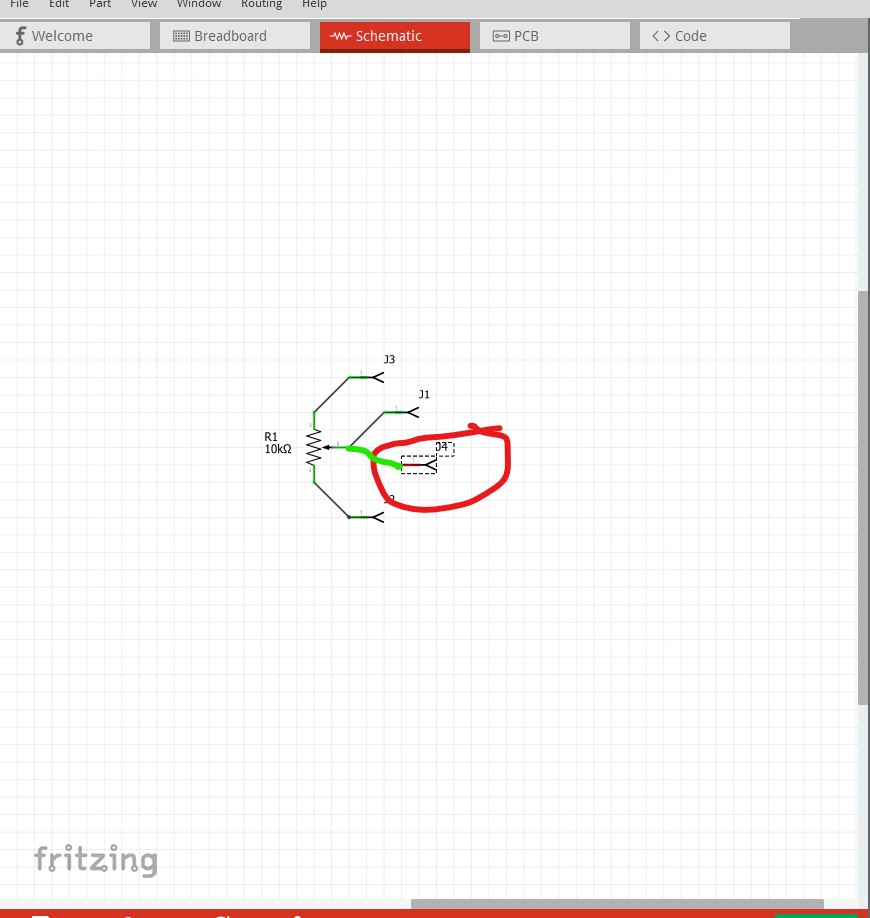
I’m currently working on an external parts factory (written in python) with the intent of suggesting that it replace the current parts factory code with a callable module (preferably user supplied callable modules that are included in the .fz file.) Then the interface to Inspector gets rewritten as an api that aims to interface to the callable modules (i.e. the code only supplies an api to interface to Inspector.) I currently have a male header (breadboard only so far) which is scalable and able to change color. Thus you supply the row, columns and pitch (and optionally a color) and it creates a header at that
pitch (with the rest of the part scaled to match that pitch.) To my mind that adds the required functionality, a python script gets the part maker access to Inspector which is very desirable. It would also enable changing hole sizes in parts (as the svg will get regenerated by the script.) Currently looks like this:

# set test parameters

part_type = "male-header"

rows = 8

columns = 2

pitch = "2.54"

pcb_type = "tht"

pad_type = "circle"

pin_order = "row"

color = "#404040"

moduleid = create_fzp(part_type, rows, columns, pitch, pcb_type)

svg = create_male_header_breadboard_svg(moduleid, part_type, rows,
                                        columns, pitch, pcb_type,
                                        pin_order, pad_type, color)

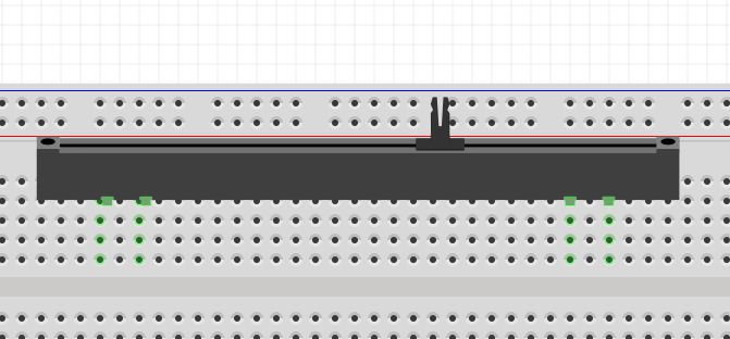
where pad_type will select a circle or oblong pcb pad once pcb is done. Currently the above generates this (a standard dual row 0.1in header which currently breadboard doesn’t do!) The row order parameter allows selecting sequential (row) where pins are

16 15 14 13 12 11 10 9
1 2 3 4 5 6 7 8

or column (with as many columns as you like) so a 3row 4column part would be numbered

3 6 9 12
2 5 8 11
1 4 7 10

or the more usual 2 column part

2 4 6
1 3 5

this is a svg of the 2.54mm 8 by 2 part above

1

.changing it to 1.27mm and color red gets this

# set test parameters

part_type = "male-header"

rows = 4

columns = 3

pitch = "1.27"

pcb_type = "tht"

pad_type = "circle"

pin_order = "row"

color = "#ff0000"

2

a 1.27mm pitch red header instead. So a single part provides any pitch you desire (pcb holes may be an issue for non standard pitch parts though!)

Peter

So the parts factory generates the properties to be used by Inspector. That is more powerful. A couple of items to note:

do not really want to write a plugin module if the only thing that is needed is to be able to set property values that do not affect the graphics

make sure that the plugins exposes the possible property names, so that inspector can switch from a non factory part in the same family, to a factory part based on the properties. Inspector needs to be able to show at least the property names for parts that have not yet been generated, if it is possible for a non-factory part to be in the same family. Or if there can be multiple factory plugin modules for the same family.

EDIT: EXTRA: the plugins would have to be included in the sketch files, to make them transportable. Just like custom parts are included.

Yes, I agree. Specially, that would be great for very specific properties of a part (that does not apply to a type of parts). Unfortunately, that is not how the code works right now.

Excellent! I looking forward to see it in action. Python is more accessible than C++ for a lot of people and bugs in the part factory would be easier to fix ans you do not have to check the rest of the code. Be sure to coordinate it with @KjellM .

Regarding the pots, I modified the slider pot to reuse the same schematic symbol as the others. As this pot has four pins, I made the second wiper “hybrid” in the schematic view. The file of the new pot is attached:
Slide Potentiometer.fzpz (6.8 KB)
. It would be great if you can spot any issues (I have not worked too much with hybrid connectors).

I committed the changes to my repository: GitHub - failiz/fritzing-parts at fix_simulator_issues However, there are some issues with a textile pot and it does not pass the CI test. The error is:
svg/core/icon/textile_strech_sensor_005.svg child element ‘style’ with no layer id
The file is just the same as the old one (the one that is in core in 0.9.10) but I just rename it. Any ideas about how to fix this error?

I figure on doing a standalone version that creates fzpz files (and since I’m using the pyside2 library to get at QT functions and thus have QT available, I may try a graphical version too :slight_smile: .) Once that is working (as it is useful on its own) then we can discuss integration. I can see a lot of issues and don’t know how easy it is going to be to get from the c++ code to python and back (the c++ code would need to provide the temp files for the .fzp and .svgs for instance that fritzing created and owns) and it may not work out. But with a working example rather than just hand waving, perhaps something will come of it. If not the standalone functionality is useful if less convenient (and likely quicker to produce than code changes to the parts factory!)

The slide pot looks fine, the hybrid doesn’t appear to be working however (possibly because of the bus):

j4 should appear floating (no connection because of the hybrid) but possibly because the two pins are bused together, it appears works correctly. I think I may have run in to this before on a bus. If you really don’t want it in schematic you can remove the connector definition in schematic in the fzp, but I think since the pin is available in both other views the way it works now is the correct answer. If you connect to both pins in breadboard or pcb it shows correctly in schamatic. I would probably remove the hybrid=“yes” in the fzp just in case this eventually gets fixed and then causes a problem in this part.

I don’t know on this one, but looking at Textile_potentiometer.svg in core parts I see its layerId is breadboard, I expect the complaint is because the layerId isn’t icon to match the .fzp file. I’d try changing the layerId to icon in the icon svg and see if that makes CI happy.

the core part was probably in place before CI was added and thus hasn’t been caught because it hasn’t changed.

Peter

I did not follow your explanation. However, after more testing I detected that it was not working properly. It worked well in the sch view you drag a connector from one of the legs of the pot to one component, but no when you draw the connection from another component to the connectors of the pot. In that case, all the pot was attaching to the second wiper (which should have been hidden in the sch).

So, I modified the FPZ file of the slider pot to remove the second wiper from the sch view. Now it looks like:

<connector id="connector3" name="wiper-1" type="male">
      <description>second wiper connection</description>
      <views>
        <breadboardView>
          <p layer="breadboard" svgId="connector3pin"/>
        </breadboardView>
        <schematicView>
        </schematicView>
        <pcbView>
          <p layer="copper0" svgId="connector3pin"/>
          <p layer="copper1" svgId="connector3pin"/>
        </pcbView>
      </views>
    </connector>

This is the new slider and seems to work properly:
Slide Potentiometer_without_hybrid_connector.fzpz (6.8 KB)
If you could test it too, it would be great.

Yes, that made the trick. The stretch sensor and the analog pressure had also similar issues. But now, all of them pass the CI tests. Thanks for your help!

Actually I prefer the first version (except as noted with the hybrid=“yes” removed.) This version leaves a connection to the wiper unconnected in schematic when in fact it is connected. My original probably wasn’t clear due to the lack of breadboard corrected here:

the second wiper connection circled in red doesn’t connect in schematic (when it did in the original version)

the connection in green should be in schematic as it actually exists I think. J4 is missing its connection to the wiper in schematic but is there in breadboard and pcb.

Peter

Aha, I could not understand it because I tested the opposite. I connected the connectors (Jx) in the SCH view and then, the behavior is correct in the BB and PCB views. The problem appears when you connect the connectors in the BB or PCB view and then the rastnets are not right in the schematic view.

Thus, I made a new version as the first one but without the “hybrid”=yes. This is the new version:
Slide Potentiometer_v3.fzpz (6.8 KB)

Of course, this also means that the SVG needs to define connector3pin and connector3terminal. That is why there were two schematic SVG files in your version. I really only want to have one schematic symbol (in the future, I hope that the simulator moves the wiper in the SCH view), so I deleted the original potentiometer_1_schematic.svg and renamed pot-slider_5_schematic.svg to potentiometer_1_schematic.svg. Thus, all the pots can share the same sch svg file. Can you spot any potential errors?

It is really a pity that the hybrid is not working well.

Yes this version looks fine. I don’t see any issues. Even if hybrid worked as expected there would still be the problem that a connection to the second wiper connection in breadboard or pcb wouldn’t connect to anything in schematic (because of the hybrid.) I don’t think this case is what hybrid is intended to fix. It is more to suppress connections entirely in a view than have one part of a bus connecting and another not.

Peter

Great. I pushed the commit. Hopefully, we will see the new potentiometers in the next release. Thanks you your help!

Doesn’t need to wait for a release, as parts they will update automatically when pushed (other than parts commit is currently broken at least on Windows :slight_smile: due to no write permissions on the parts db.)

You are most welcome. This is a good start on cleaning up core parts!

Peter

I believe that the parts database update (download changes) has been disabled in recent Fritzing versions. It was causing too many issues. From being broken in some environments, to startup problems because it appeared frozen, and restarts were leaving things corrupted. The intent I saw in some messages (not this forum) was that with a faster application update cycle, including that core parts database with the application would be sufficient. People with the right knowledge can do updates from outside of Fritzing. I don’t necessarily aggree with that assessment, but I am one of the people that can figure out how to fix things when they go off track.

Interesting! I hadn’t seen any parts updates but also no pull requests on github (Including from me :slight_smile: ) to cause any. That may be why the problem report on regenerate the database not working appears to be being ignored.

Peter

Yet another project that has run in to “needs a parts policy” some of the 7805 voltage regulators in core parts are incorrect. However fixing them is going to be exciting. See

for additional details. Basically a bunch of the voltage regulators share svgs, but the svgs are bendable leg and the fzp files (at least some of them) are not. It seems to me the sensible way forward is a policy on svg sharing of some kind (with then normal answer being don’t share because it causes maintenance problems.) I’m looking for a way forward, preferably with wide consultation from people with an interest in making parts, to getting such a policy in place.

Peter

Hi Peter,
@KjellM has detected an error in the slider potentiometer that I submitted to the repository, see below:
image
Is there any reason for not having the pins aligned with the breadboard?

As this is a new potentiometer part (that does not replace the old one), we could even make new potentiometer that is available. Thoughts?

No, I just didn’t do it because the actual pot didn’t align to the breadboard.

I think that would be preferable. Then the url can point to an available pot if the user wants one.

Peter

The current one aligns with the board and has only three pins:
image

Do you have another part for a linear pot that is available to buy?

A quick google search turns up this one (Alps is a fairly common brand as well)

https://www.mouser.ca/datasheet/2/15/RS__1-1370683.pdf

edit:

This is probably a more useful form though

slide-pot-alps-rs1.fzpz (4.2 KB)

It uses the new schematic svg and aligns to the grid in breadboard.

Peter

Hi,
It seems good to me. The only thing I am a bit worried is that in breadboard view, the pot is not so easy to connect. The only way of using it, it is rotated it 90 degrees, see below. Then the wires look a bit weird as they are drawn on top of the pot, when there would be below the pot. If you do not rotate it, then two or the pins are short circuited.

In any case, this layout seems very standard. I checked a bit and I could not find any that fits well in a breadboard (except if it is a pot soldered on a PCB).

@KjellM , what do you think? Should we replace the old slider pot with the new one?

edit: Or should we make a pot soldered on a PCB in the breadboard view?

I saw that problem, we could cheat in one of three ways. Move the top pin up 0.1in to make it fit the breadboard (but not in real life!) , use an SMD style adapter (probably the better choice!) to indicate an adapter board is needed to fit a breadboard or make the top pin female so it won’t connect to the breadboard but will connect to a wire. I may also make the body more three dimensional as well, probably be stealing the current slide pot body. As well this will work with the current part (although making the top pin female would still be a good bet to prevent the short if plugged in wrong!)

This may be the best option since it most closely matches real life.

edit:

Here is a new part (same moduleId as the first one so you will need to delete that to load this) with some changes to make it more usable on breadboard.

edit2:

An improved version which is wider in the body (but the same length) you will need to remove the old version to load this one as the moduleId is the same.

edit3:

Yet another attempt. Fix the perspective and make breadboard reflect real life better by placing the top pin where it should be and adding the necessary wire to connect it to breadboard (which you would need to do in real life to make it work!)

edit4: Another attempt at a better part.

slide-pot-alps-rs1-improved.fzpz (5.7 KB)

The new part

fits on the breadboard

but varies from real life in that pin 0 is offset 0.1in in X from where it should be to accommodate the breadboard. The image is much better than the original as well (swiped from the original slide pot.)

edit:

The latest version

Peter