Aha, I could not understand it because I tested the opposite. I connected the connectors (Jx) in the SCH view and then, the behavior is correct in the BB and PCB views. The problem appears when you connect the connectors in the BB or PCB view and then the rastnets are not right in the schematic view.
Thus, I made a new version as the first one but without the “hybrid”=yes. This is the new version: Slide Potentiometer_v3.fzpz (6.8 KB)
Of course, this also means that the SVG needs to define connector3pin and connector3terminal. That is why there were two schematic SVG files in your version. I really only want to have one schematic symbol (in the future, I hope that the simulator moves the wiper in the SCH view), so I deleted the original potentiometer_1_schematic.svg and renamed pot-slider_5_schematic.svg to potentiometer_1_schematic.svg. Thus, all the pots can share the same sch svg file. Can you spot any potential errors?
It is really a pity that the hybrid is not working well.
Yes this version looks fine. I don’t see any issues. Even if hybrid worked as expected there would still be the problem that a connection to the second wiper connection in breadboard or pcb wouldn’t connect to anything in schematic (because of the hybrid.) I don’t think this case is what hybrid is intended to fix. It is more to suppress connections entirely in a view than have one part of a bus connecting and another not.
Doesn’t need to wait for a release, as parts they will update automatically when pushed (other than parts commit is currently broken at least on Windows due to no write permissions on the parts db.)
You are most welcome. This is a good start on cleaning up core parts!
I believe that the parts database update (download changes) has been disabled in recent Fritzing versions. It was causing too many issues. From being broken in some environments, to startup problems because it appeared frozen, and restarts were leaving things corrupted. The intent I saw in some messages (not this forum) was that with a faster application update cycle, including that core parts database with the application would be sufficient. People with the right knowledge can do updates from outside of Fritzing. I don’t necessarily aggree with that assessment, but I am one of the people that can figure out how to fix things when they go off track.
Interesting! I hadn’t seen any parts updates but also no pull requests on github (Including from me ) to cause any. That may be why the problem report on regenerate the database not working appears to be being ignored.
Yet another project that has run in to “needs a parts policy” some of the 7805 voltage regulators in core parts are incorrect. However fixing them is going to be exciting. See
for additional details. Basically a bunch of the voltage regulators share svgs, but the svgs are bendable leg and the fzp files (at least some of them) are not. It seems to me the sensible way forward is a policy on svg sharing of some kind (with then normal answer being don’t share because it causes maintenance problems.) I’m looking for a way forward, preferably with wide consultation from people with an interest in making parts, to getting such a policy in place.
Hi Peter, @KjellM has detected an error in the slider potentiometer that I submitted to the repository, see below:
Is there any reason for not having the pins aligned with the breadboard?
As this is a new potentiometer part (that does not replace the old one), we could even make new potentiometer that is available. Thoughts?
Hi,
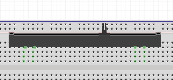
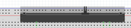
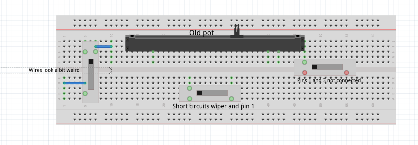
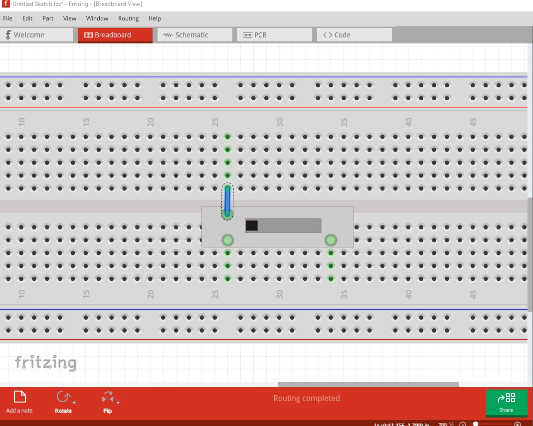
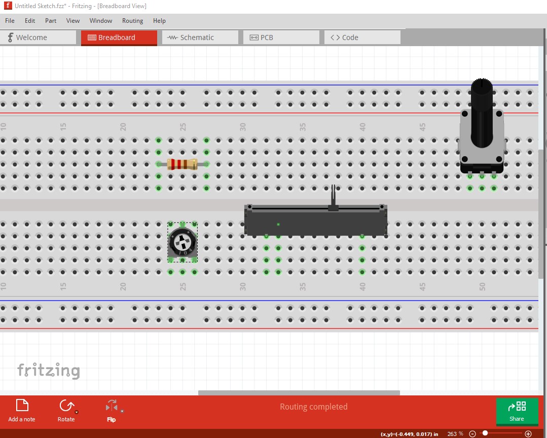
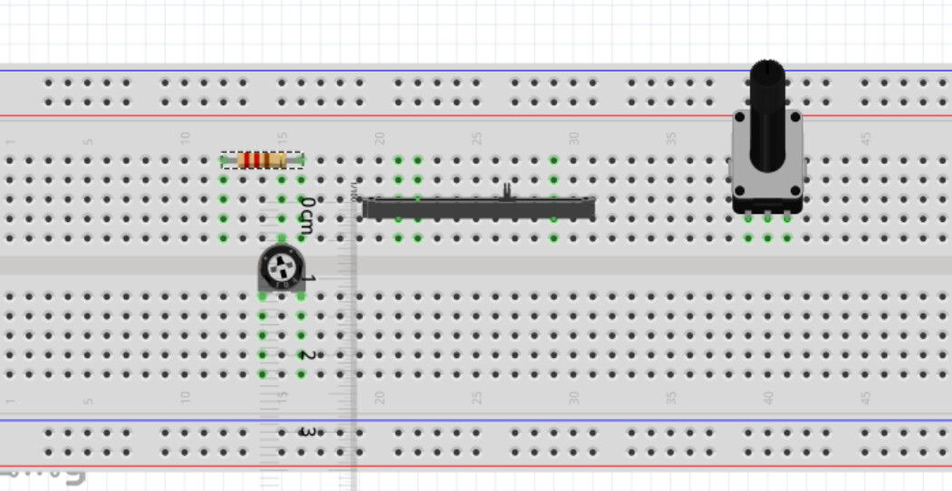
It seems good to me. The only thing I am a bit worried is that in breadboard view, the pot is not so easy to connect. The only way of using it, it is rotated it 90 degrees, see below. Then the wires look a bit weird as they are drawn on top of the pot, when there would be below the pot. If you do not rotate it, then two or the pins are short circuited.
In any case, this layout seems very standard. I checked a bit and I could not find any that fits well in a breadboard (except if it is a pot soldered on a PCB).
@KjellM , what do you think? Should we replace the old slider pot with the new one?
edit: Or should we make a pot soldered on a PCB in the breadboard view?
I saw that problem, we could cheat in one of three ways. Move the top pin up 0.1in to make it fit the breadboard (but not in real life!) , use an SMD style adapter (probably the better choice!) to indicate an adapter board is needed to fit a breadboard or make the top pin female so it won’t connect to the breadboard but will connect to a wire. I may also make the body more three dimensional as well, probably be stealing the current slide pot body. As well this will work with the current part (although making the top pin female would still be a good bet to prevent the short if plugged in wrong!)
This may be the best option since it most closely matches real life.
edit:
Here is a new part (same moduleId as the first one so you will need to delete that to load this) with some changes to make it more usable on breadboard.
edit2:
An improved version which is wider in the body (but the same length) you will need to remove the old version to load this one as the moduleId is the same.
edit3:
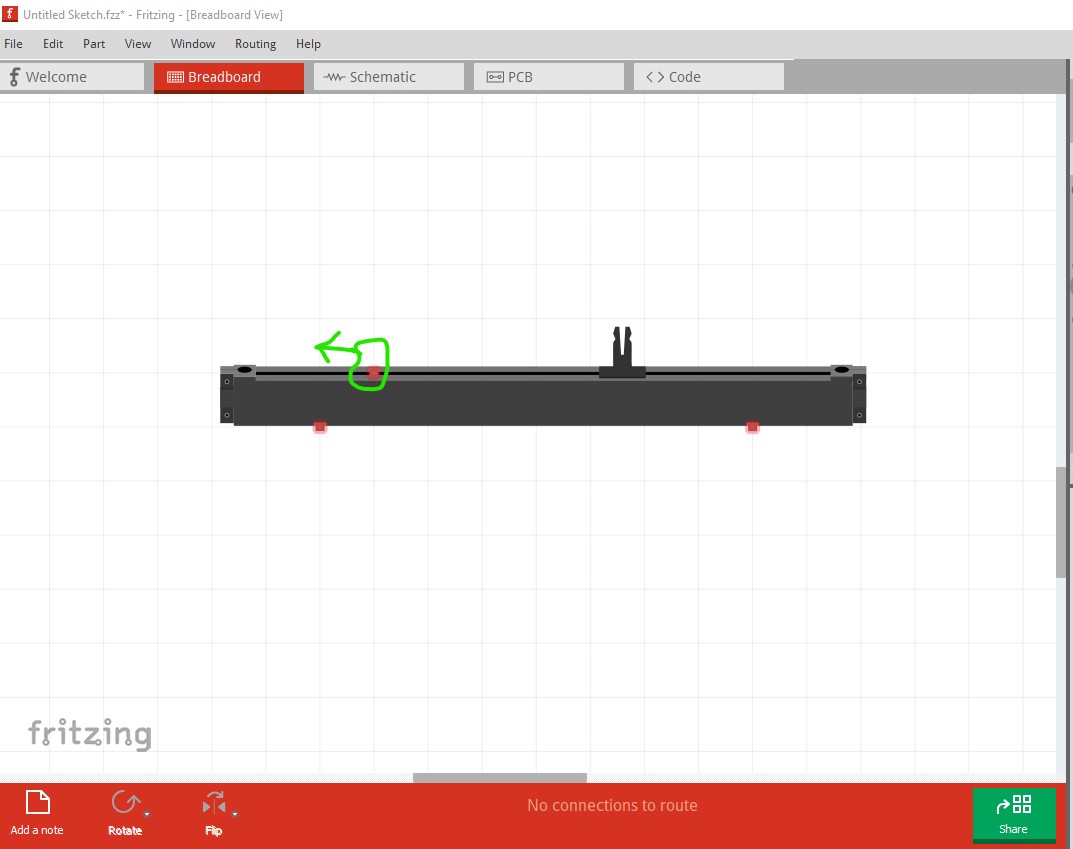
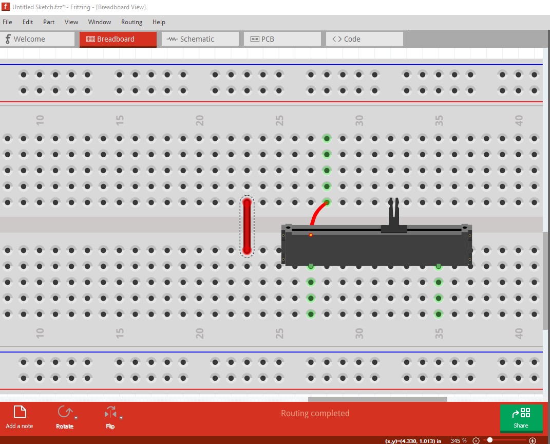
Yet another attempt. Fix the perspective and make breadboard reflect real life better by placing the top pin where it should be and adding the necessary wire to connect it to breadboard (which you would need to do in real life to make it work!)
but varies from real life in that pin 0 is offset 0.1in in X from where it should be to accommodate the breadboard. The image is much better than the original as well (swiped from the original slide pot.)
In the BB view, the pot is very small. The length is ok, but the width is smaller than the real world (probably caused by scaling the original image). The pot looks just slightly bigger than the resistor and much smaller than the other pots
That is true (as is the scaling) but it is the correct length for the real pot. It can be made wider (although the perspective may then be off.) I’ll poke at it a bit.
edit: I replaced the original part with one which is higher in the post above.
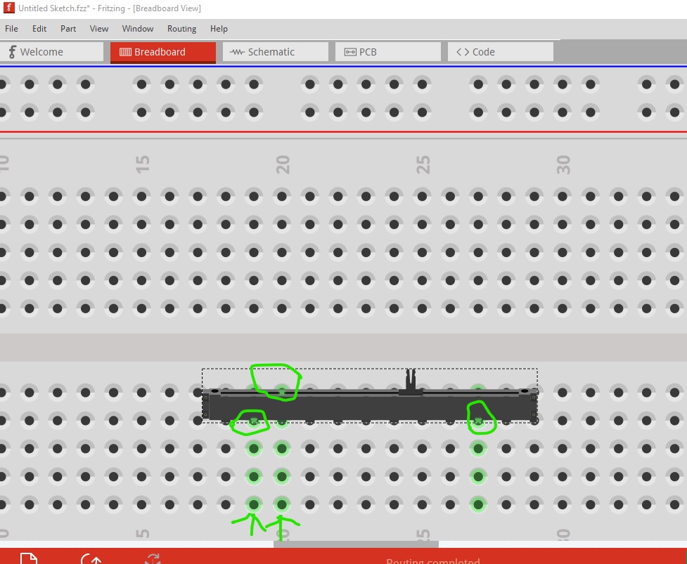
Getting better, but I think the perspective is a bit odd. Did you scale in one direction? If yuou observe the holes at the top, they were ovals before and now they are circles. And the side holes were circles and now are ovals. That distorsions the perspective.
I would say that rather than scaling, what the picture needs is reducing the lenght of the middle part, but without scaling the sides. Other option is to go for a longer pot, similar size that the original.
Another attempt with the ellipses and circles corrected and a new (I think better) contact arrangement with a wire to the pin that won’t connect to the breadboard.
Part above replaced.
Getting better!
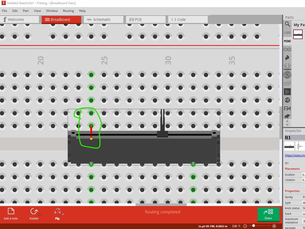
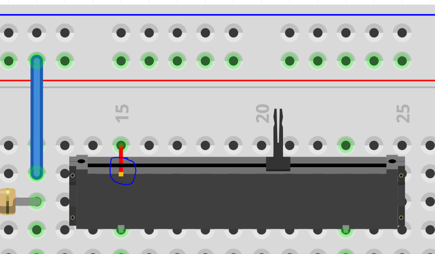
Maybe the knob also needs to be adjusted, it seems compressed horizontally. And the wire should not be visible when it is behind the pot (blue area highlighted) and I would try to make the wire similar to the wires in Fritzing (some people may not recognize the red line as a wire).
Technically no, the gold square isn’t a connector so it won’t short although you could place it so the wire would short. In this version I increased the horizontal size of the slider and changed the wire so that it can’t short no matter what and indicated where the wire connects to the pot (on the real life pin position although it isn’t a Fritzing connector and thus won’t short.)