Suggestions for additional documentation

The following is a list of additions/changes (mostly additions) I would like to see be made to the parts standard. Some of then will probably be controversial and the list is likely not complete (so if you have additions feel free to add them to the discussion!) This post came about from this suggested revision to core parts. I am of the opinion we need to settle some of the issues listed below to allow this fairly major change to parts to be done only once (correcting as many issues as we can!)

The first issue is a question about the code more than parts.

  • In the fzp file what does

    4

do (if anything?) most parts seem to be version 4, but is that significant for anything, or is it supposed to be the version of the part? I.e. should it start at 1 (for version 1) and increase by 1 for each new version of the same part or is it significant in the code for some reason. A look at the source doesn’t tell me what if anything looks at it in Fritzing and I don’t know what the original purpose was or if anything in the code depends on the version number. I have made parts with version 1 and they seem to work fine, but that isn’t a definite answer to the question. Many of the part templates use version 4:

owner@owner-PC /cygdrive/d/repos/fritzing-app-cur
$ grep -R ‘4’ *
fritzing-app/resources/parts/core/30.20PerfboardModuleID.fzp: 4
fritzing-app/resources/parts/core/30.20Stripboard2ModuleID.fzp: 4
fritzing-app/resources/parts/core/30.20StripboardModuleID.fzp: 4
fritzing-app/resources/parts/core/blocker.fzp: 4
fritzing-app/resources/parts/core/blocker0.fzp: 4
fritzing-app/resources/parts/core/boardlogoimage.fzp: 4
fritzing-app/resources/parts/core/boardlogoimage_one_layer.fzp: 4

but none appear to use any other version except for 2 in some obsolete parts apparantely for old headers which may mean the version matters for the code:

owner@owner-PC /cygdrive/d/repos/fritzing-app-cur
$ grep -R ‘1’ *

owner@owner-PC /cygdrive/d/repos/fritzing-app-cur
$ grep -R ‘2’ *
fritzing-app/tools/scripts/obsolete/cheetah scripts/templates/generic-female-header-rounded.fzp-save: 2
fritzing-app/tools/scripts/obsolete/cheetah scripts/templates/generic-female-header.fzp-save: 2
fritzing-app/tools/scripts/obsolete/cheetah scripts/templates/generic-male-header.fzp-save: 2
fritzing-app/tools/scripts/obsolete/cheetah scripts/templates/screw_terminal.fzp-save: 2
tools/scripts/obsolete/cheetah scripts/templates/generic-female-header-rounded.fzp-save: 2
tools/scripts/obsolete/cheetah scripts/templates/generic-female-header.fzp-save: 2
tools/scripts/obsolete/cheetah scripts/templates/generic-male-header.fzp-save: 2
tools/scripts/obsolete/cheetah scripts/templates/screw_terminal.fzp-save: 2

owner@owner-PC /cygdrive/d/repos/fritzing-app-cur
$ grep -R ‘3’ *

owner@owner-PC /cygdrive/d/repos/fritzing-app-cur
$ grep -R ‘5’ *

I think we need to figure out what version is intended to be used for and set up a standard value for it (such as start at 1 for the first instance of a part and increase it by 1 for new versions of the same part!) or if necessary leave it at the current setting of 4 if that is significant to the code for some reason.

The rest of these are suggestions for new or changed standards for parts (i.e. changes to the parts standard document here:

and perhaps to the graphics standards here:

https://fritzing.org/fritzings-graphic-standards

  1. no blanks in file names, replace with underscore.

reason:
convenience, don’t have to quote file names in unix!

  1. file names must be identical case in the .fzp file and the file system.

    reason:

On Unix (Linux and the Mac) case matters, and if it isn’t identical the part won’t work on Linux or the Mac. Because Windows is not case sensitive in filenames,it will work on Windows which makes it an easy mistake to make if you are creating parts on Windows. There are a number of parts in core parts that have this problem now (FritzingCheckPart will issue a warning about them!)

  1. scale 10.41667 (in Inkscape) as of inkscape-1.1.2_2022-02-04_0a00cf5339 this has changed to 1000 (as the scale appears to now be in inches) if the drawing units are set in in!

    reason:

to make the viewbox a 1/100 ratio as specified in the parts file format. This means that drawing units are in 1 thousndth of an inch making calculatig positions in parts easier. I assume that is why it is specified in the part file format (but don’t know for sure!)

  1. svg dimensions in or mm (not blank or px as blank defaults to px!)

reason:

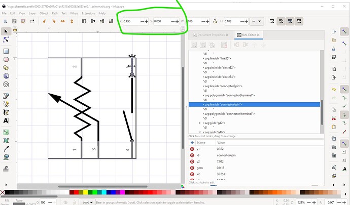
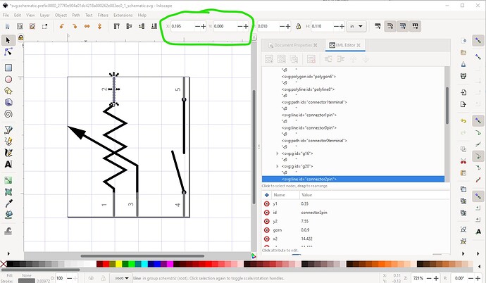
Px causes scaling problems editing the svg. There are at least 2 common DPI settings, 72DPI (early Illustrator and maybe Inkscape), 90 DPI (original SVG standard?) earlier versions of Inkscape, 96DPI current SVG standard and current Inkscape. Having dimensions in px will display the image in the wrong scale in the svg editor. This svg was created by editing the “dial pot with switch” part in core parts in parts editor, saving it as a new part, then exporting it and unzipping it to get the schematic svg. Note the parts editor (in Fritzing 0.9.9 at least) corrects the svg units to in to make sure the image is correct!

We see the pin2 starting x coord is on a 0.1in boundary as is the the pin5 x coord shown in this image and thus all is well.

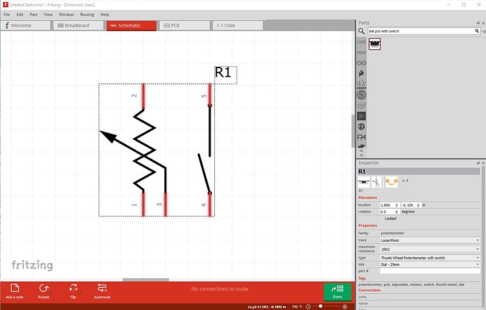
This is what it looks like in Fritzing (which will guess that the DPI in use was 72DPI and scale it correctly)

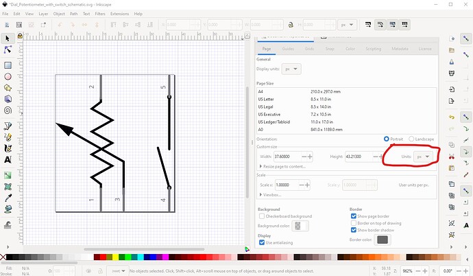
This is the svg in core parts displayed in Inkscape (-1.1.2_2022-02-04_0a00cf5339 currently latest version)

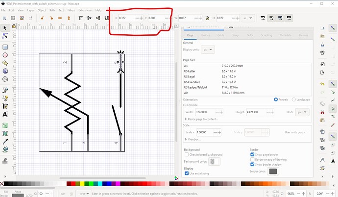
Note the Units (circled in red) is in px. This causes the scale to be incorrect like this (compared to the version output by parts editor!)

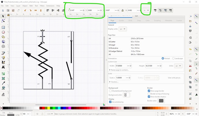
If we take the origin of pin 2 here (circled in green) as the start point, we see that pin 5 is mis aligned

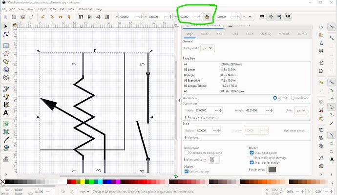
the x coord should be 0.447in not 0.372in. The scale is similarly off in y as the current Inkscape is using 96DPI and the original svg is using 72dpi. To convert I set the units to %, locked width to height and set the width to 133.3333333333333% (72/96) which converts the scale to be correct like this:

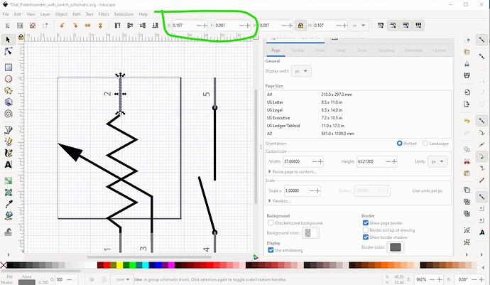
the 100% in width was set to 133.3333333333333% to rescale the svg resulting in this which is now the correct scale and can have its units changed to in

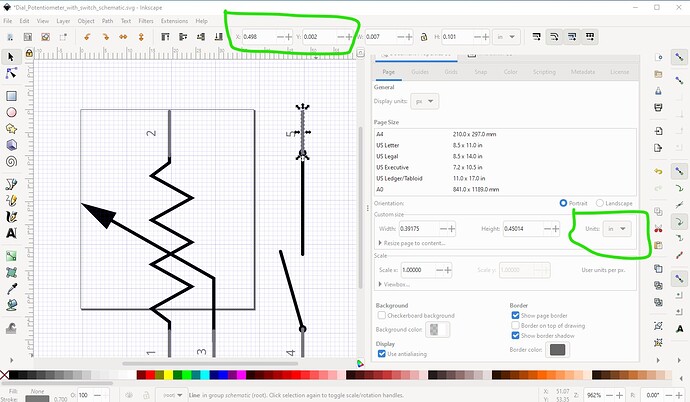
Here pin 2 starting x is 0.197in and pin 5 is 0.498in as it should be.

and the units have been changed to in so when resized and saved this svg will now be correct (no matter what dpi the editor is using!) Making the units in (or mm) sets the size of the svg to a real world value and eliminates the editor DPI setting from the equation.

  1. In breadboard parts not on 0.1in pitch have an adapter board to make the pins 0.1in spaced in breadboard view.

reason:

None 0.1in parts won’t fit on a breadboard. This is commonly done for SMD ICs (most of which have an adapter board in breadboard), I am suggesting it be usually done for everything. There will likely be exceptions such as 2mm/1.27mm/1mm connectors in modules (although the 1.27 and 1mm ones get hard to attach wires to in breadboard!) and for modules of various kinds that aren’t on 0.1in boundaries (buck and boost power supplies are one example! The Arduinos are another.) Leave this one as a recommendation if possible, not a requirement?

  1. standard label field tags

reason:

Consistantcy, at present there is no guidance, ICs are sometimes U (which I think is mostly the standard in other EDAs) but sometimes IC (which isn’t standard)for example the generic IC has a label of IC not U. This one will require a code change to the parts factory to correct but I think should be done. For modules (again boost and buck power supply modules are one example) I use a label field of M (for module.) Should we make that the standard? I would like to see it so. Once we decide on this, then we need to go through core parts and fix anything that doesn’t meet this standard.

  1. pcb silkscreen should match the part outline.

reason:

Placing the part in pcb so the silkscreen does not overlap with other components should result in a board where the real components will fit. At present this is mostly how parts are, but there are some (some of the pots where, this discussion started from, are an example) where that is not true and I think it should be made the standard because it is useful when laying out boards!

  1. Top-view parts

reason:

Top-view parts are a modification of (typically) descrete components such as LEDs to fit within their pcb footprint for use on perfboard. Instead of the standard 3d representation tilted at a 45 degree angle (and taking up much more space than the real part!) they are reduced (typically by making the view from the top straight down, thus the name!) to fit in the same space they would occupy in pcb view. This point is mostly to document that these types of parts exist.

  1. connector not a group

reason:

With the pins at the bottom of the svg in xml editor and the first pin labeled as connector, I have python scripts that will assign the pin and terminal numbers which saves a lot of typing when modifying svgs. I think that is worth making this a standard best practice.

  1. re use breadboard svg as icon svg

reason:

Normally they are identical, this saves the disk space of the icon svg if it is (as usual) same as the breadboard svg.

<views>
  <iconView>
    <layers   image="breadboard/6mm-trim-pot_4dbcc911bf18e42b869be34c5c5077b6_1_breadboard.svg">
      <layer layerId="icon"/>
    </layers>
  </iconView>

works just fine. That is my current list. Additions and comments welcome!

Peter

Great initiative Peter!
Sorry for the late reply, I have been busy with my classes.
I agree with most of this. Just a few comments.

The version indeed needs to be clarified. I thought that it was the version of the part rather than a version of the format of the part. That field is loaded in ModelPartShared and can be accessed through the version() call. I think it is used only to show in the version number in the inspector pane. I used this command to count the number of parts in the core with different versions: grep -o "<version>1" * | wc -l These are the results:
Number of parts with version 1: 133
Number of parts with version 2: 16
Number of parts with version 3: 0
Number of parts with version 4: 1441
Number of parts with version 5: 77
Number of parts with version 6: 8
Number of parts with version 7: 2
Number of parts with version 8 or above: 0

So, I think it is just the version of the Fritzing part and has nothing to do with the format version of the part. @KjellM , any thoughts on this?

Another thing to document would be the Fritzing version. Does it need the latest version of Fritzing or the highest version of Fritzing where the part works? When updating a new part, should we increase the Fritzing version in the updated part?

I agree. All of them should be U. Not sure about the M. It looks that M is used for motors. Reference designator - Wikipedia
These two links suggest using A for modules or plug in assemblies:
S6.1 Component Reference Designator (RefDes) - Library Conventions | KiCad EDA
Reference designator for components - Page 1

Top view needs to be included in the core parts. This would be pretty easy to do, but maybe we need to check that all top view parts follow the new standards. In the future, it could be maybe integrated into the preferences menu or with a check button in the inspector pane.

We should also create and decide a taxonomy for the most important families and their properties. So, the swapping part works well, when they are added to the existing family. For example, there are “rotary encoder” and “rotary encoders” families in the core.

This should (normally) be the Fritzing version the part was created with (for). Certain things have changed over time, and this lets the Fritzing code ‘adjust’ some settings on the fly (for backward compatibility of the parts). For new (or updated) parts, it should be the current Frtizing version. Or the version of Fritzing the part was tested against. Really, it specifies the ‘rules’ that were used to create the part.

As noted in

There are a couple of items (terminalIds and through hole pads not being paths) which are not always incorrect, but will sometimes not work in difficult to detect cases. I think the appropriate action here is to specify in the part file format (or other tbd documentation!) that terminalIds and through hole pads need to be a rectangle and a circle respectively.

Peter

With the caveat that additional elements can be used to change the shape of the pads. A circle is need to reliably get the hole drilled, but additional (path or other) elements can be used to adjust the pad outline.

Better late than never I guess, I have been lazy about doing the svgs for you, but I have finally finished. First a list of issues for discussion that came up while cleaning up these parts (and incorporating some of the suggestions above!):

Issues for concideration/discussion:

  1. fzp version number

    1

    Start at 1 and increase by 1 for each new version. Append to the end of the moduleId (i.e. moduleId-text_1) and file names (fzp-name_1.fzp, svg-name_1.layrId.svg (i.e. part-name_1.breadboard.svg) all of which increase by 1 for each new version so file names are unique within the part repository.

  2. svg name unique to this part only.

    svg names should be unique to the part so that a change does not affect any other part in most case. The potentiometers in this case are an exception because it is desirable for the schematic svg to be common for all pots! This avoids a change in one part accidentally affecting many parts which I think is the better option than saving some space in the repository by sharing svgs.

  3. Avoid blanks and brackets “(” and “)” in file names.

    Avoiding blanks in file and svg names means that you don’t need to rememeber to quote the file name (which you must if it contains blanks!) on Unix (and sometimes Windows) which I think is worth doing. Use either an underscore or a minus sign in place of the blank. Brackets make using regular expressions to find file names more difficult.

  4. Connectors should be invisible

    Connectors should be invisible (i.e. fill=none stroke=none stroke-width=0) so they can be moved to the bottom of the svg to make tools that renumber svgs easier (so that moving a connector to the bottom does not affect the appearance of the svg!)

  5. Connectors should be a drawing element not a group.

    While specifying a group name as a connector works (Fritzing appears to use the first drawing element of the group as the connector) if you ungroup the svg the connectors are all lost. I think it is worthwhile to not allow groups to be connectors for that reason (ungrouping the svg will make the part not work anymore because the connectors are gone!) The breadboards are the most notable example of this in core parts although there are probably others. The development version of FrtizingCheckPart corrects this.

  6. Connectors should be in pin order and the last thing in the svg.

    Doing this allows renumbering svg files with a python script by scanning for the first occurance of connector (or connector0 as you choose) and then assuming all elements after that are connectors which should increase in pin number by 1 for each new connection. I have and use python scripts that do this, although they need some additional work on options to be releasable.

  7. Svg file names should end in the layerId

    For consistancy (many parts are already this way) the svg name should end with layerId.svg (i.e. basic_fsr_5_breaboard.svg rather than basic_fsr_5.svg) so it is obvious what layer the svg file is for.

  8. No present source for the part.

    If we can not find a commercial source for the part should we just delete it as no longer being useful? I’m inclined to say yes as we can’t get them anywhere. They probably then need to move to obsolete parts so previous sketches still work but I think we should clean up the parts bins by deleting parts that are no longer available. So far I have found and substituted alternate parts for those not found though except as noted for the textile pots, tbey appear to be gone with no available replacement. As part of this require a url to a source of the part, so we know when a part is no longer available. The slide pot is one example of this. I can’t find an example of a 2.5in slide pot that has a pcb foot print that matches the part. There obviously was one when the part was made, but there is no url (or manufacturer) in the part to tell us where we might source it. A source of the part seem like a good idea to me.

  9. PCB pin for through hole part pad for SMD part.

    Through hole parts should have pcb connectors end in pin and SMD in pad.

10)Fritzing version, what to update it to in a part.

I'm inclined to update it to the current version of Fritzing that you have tested the new part on. That may be unwise (at least without a lot of care!) for parts that have older version dependent elements (for example older model pin headers, change to the current version based on a hard coded Fritzing version. Recognizing this is happening will likely be an issue, as it isn't something most parts makers are going to take in to accout. It may be that we need to figure out all the cases where this currently occurs and add a test to FritzingCheckPart.py to warn about 
  1. label field standard.

    I have switched from label M (for modulei which conflicts with M for motor) to label A (for assembly) for boards. It would be good to have a standard list for common parts (such as J for jack, U for ICs although parts factory is using IC as the label not U and I’d like to see that change!)

  2. parts bin layout

    I think we need to do a major clean up on the part bins. I agree a onomy for the most important families and their properties would be useful along with guidelines for selecting a family name. This may get tricky to get agreement on though, but I think it is worth doing. I’d like to be able to do something like search for “motor driver” and come up with all the available motor driver parts so I can choose one.

  3. Search parameters cleanup

    Search is currently a mess.

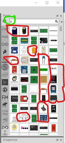
This is a search for ic. I would expect this to bring up all the ics (which it in fact may do!) but why also electrolytic caps (and multiple copies of the same electrolytic cap) boards, switches etc. I’m not sure what can be done about this, but something better than what we have now would be good.

  1. What to do about parts that are no longer available?

    The 3 textile pots below are in this category. The manufacturer has apparently gone under and there don’t appear to be any replacements. It will be useful to have the current parts in at least the obsolete parts bin so existing sketches from when they were available still work, but they shouldn’t show up in a search (?) as they aren’t available if you don’t already have one. I’m not sure what the best way to handle this is.

Peter

That said now on to the potentiometer clean up project. I have finally finished looking over the ones you sent and have created this zip file of the .fzp files in repository format (i.e. core/fzp-files and svg/core/layerId/svg files.) Along with the list of changes that I made and why. The ones in this repository have all been run through FritzingCheckPart.py and thus (as long as the svgs are not edited in Inkscape again!) should be ready to go. Of note are the three textile pot parts, I didn’t do anything with them because they are all no longer made and there don’t appear to be any reasonable replacements around. So I think we should probably just obsolete them as being no longer available.

This is actually a zip file of the repository not really a .fzpz file as it says!

temp_vanepp.fzpz (65.2 KB)

A list of changes that I made and why:

Rename

/cygdrive/d/fritzing-backup/imported-parts/temp_vanepp/core/force_sensor_resistor_circular_05in_005.fzp

to

/cygdrive/d/fritzing-backup/imported-parts/temp_vanepp/core/force_sensor_resistor_025in_6in_5.fzp

orig in core parts

fritzing-parts/core/Basic Force Sensing Resistor (FSR).fzp"

change file name from

force_sensor_resistor_025in_6in_005.fzp

to

force_sensor_resistor_025in_6in_5.fzp

change

module fritzingVersion="0.4.1b.07.17.4356" moduleId="force_sensor_resistor_025in_6in_005_dpe3onv"

to

module fritzingVersion="0.9.9" moduleId="force_sensor_resistor_025in_6in_5"

i.e current Fritzing version 0.9.9 and moduleId matches version setting (_5).

change

<author>Unknown (modified by A. Faina)</author>

to

<author>tigoe (modified by A. Faina)</author> 

to preserve the orignal author’s name

change

<tag>Felx Sensor</tag>

to

<tag>Flex Sensor</tag>

correct apparent typo.

change

<layers image="breadboard/Basic_Force_Sensing_Resistor_(FSR)__a4ff.svg">

to

<layers image="breadboard/Basic_Force_Sensing_Resistor_FSR_5_breadboard.svg">

to create a unique svg name that matches the version number and to match the format of many other parts (i.e part-name_version-no_layerId.svg). As well remove the brackets from the file name.

change

 <layers image="schematic/rheostat_schematic.svg">

to

 <layers image="schematic/rheostat_1_schematic.svg">

to give it a version number (even though it isn’t the same as this parts version number because it is a new file!) and the layerId.

change

<layers image="pcb/Basic_Force_Sensing_Resistor_(FSR)__a4ff.svg">	

to

<layers image="pcb/Basic_Force_Sensing_Resistor_FSR_5_pcb.svg">

to match the naming convention

change

<layers image="icon/Basic_Force_Sensing_Resistor_(FSR)__a4ff.svg">

to

<layers image="breadboard/Basic_Force_Sensing_Resistor_FSR_5_breadboard.svg">

to match the new breadboard svg name.

change

<connector id="connector0" name="Pin 2" type="male">
  <description>Pin 2</description>	

to

<connector id="connector0" name="Pin 1" type="male">
  <description>Pin 1</description>		

to make connector0 be pin 1 as is the usual practice rather than pin2 as it was.

change

<connector id="connector1" name="pin 1" type="male">
  <description>Pin 1</description>	 

to

<connector id="connector1" name="pin 2" type="male">
  <description>Pin 2</description>

to make connector1 be pin2 as is the usual practice in other parts.

add

https://www.sparkfun.com/products/8606

to add a URL to one source of such a part.

In D:\Fritzing-backup\imported-parts\temp_vanepp\svg\core\breadboard\Basic_Force_Sensing_Resistor_(FSR)_5_breadboard.svg

change file name from

Basic_Force_Sensing_Resistor_(FSR)_5_breadboard.svg

to

Basic_Force_Sensing_Resistor_FSR_5_breadboard.svg

change scale from 72 to 1000 to match the parts file format. Dimensions are correct in inches already.

Move the connectors in order to the bottom of the svg. This has no operational effect, but is required for some tools I have that renumber connections to be able to automatically renumber svg pins.

copy

breadboard/Basic_Force_Sensing_Resistor_FSR_5_breadboard.svg

to

icon/Basic_Force_Sensing_Resistor_FSR_5_icon.svg

to create an icon file. While in a .fzpz file reusing the breadboard svg as the icon works, I can not see any part in core parts that does not have an icon svg in the icon dirctory (indicating that the loader may add one from a .fzpz file and thus there may need to be a second copy of the breadboard file in the icon directory in core parts!) So maintain (apparent) existing practice and create an icon file.

Schematic is replaced by the new reostat schematic

pcb is replaced by a new pcb svg (basically identical to the original) except for that it exists in the core parts repository (the current one is a special file that Fritzing creates which can be confusing!)

D:\Fritzing-backup\imported-parts\temp_vanepp\core\force_sensor_resistor_circular_05in_005.fzp

change file name from

force_sensor_resistor_circular_05in_005.fzp

to

force_sensor_resistor_circular_05in_5.fzp

change

<module fritzingVersion="0.1.1201" moduleId="force_sensor_resistor_circular_05in_005_icb7s6u">

to

<module fritzingVersion="0.9.9" moduleId="force_sensor_resistor_circular_05in_5">

change

<layers image="icon/basic_fsr.svg">

to

<layers image="icon/basic_fsr_5_icon.svg">

change

<layers image="breadboard/basic_fsr.svg">

to

<layers image="breadboard/basic_fsr_5_breadboard.svg">

change

<layers image="schematic/rheostat_schematic.svg">

to

<layers image="schematic/rheostat_1_schematic.svg">

change

<layers image="pcb/jumper_2_100mil_pcb.svg">

to

<layers image="pcb/basic_fsr_5_pcb.svg">

change

    <connector id="connector0" name="pin 0" type="male">
        <description>Pin 1</description>

to

    <connector id="connector0" name="pin 1" type="male">
        <description>Pin 1</description>

so both parts of the descption refer to pin 1 rather than one as pin 0 and the other as pin 1.

change

    <connector id="connector1" name="pin 1" type="male">
        <description>Pin 2</description>			

to

    <connector id="connector1" name="pin 2" type="male">
        <description>Pin 2</description>

again so the pin numbers are consistant in the pin. Rather than confusing.

add

</connectors>
<url>https://www.sparkfun.com/products/9375</url>

to provide a url to one source of the referenced part.

D:\Fritzing-backup\imported-parts\temp_vanepp\svg\core\breadboard\basic_fsr.svg from core parts

rename file from

basic_fsr.svg

to

basic_fsr_5_breadboard.svg

change scale from 100 to 1000, already dimensioned in inches.

Move the connectors to the bottom of the svg.

icon

copy breadboard/basic_fsr_5_breadboard.svg to icon/basic_fsr_5_icon.svg

schematic is the new reostat schematic “rheostat_1_schematic.svg” again.

pcb

copy Basic_Force_Sensing_Resistor_FSR_5_pcb.svg to basic_fsr_5_pcb.svg

D:\Fritzing-backup\imported-parts\temp_vanepp\core\potentiometer_dial_switch_005.fzp

rename

potentiometer_dial_switch_005.fzp

to

potentiometer_dial_switch_5.fzp

change

<module fritzingVersion="0.9.9" moduleId="potentiometer_dial_switch_005_f3wriih_PotentiometerModuleID">

to

<module fritzingVersion="0.9.9" moduleId="potentiometer_dial_switch_5">

change

        <layers image="icon/Dial_Potentiometer_with_switch.svg">

to

        <layers image="icon/Dial_Potentiometer_with_switch_5_icon.svg">

change

       <layers image="breadboard/potentiometer_w_switch.svg">

to

       <layers image="breadboard/potentiometer_w_switch_5_breadboard.svg">

change

        <layers image="schematic/potentiometer_with_switch_schematic.svg">

to new svg

        <layers image="schematic/potentiometer_with_switch_1_schematic.svg">

change

        <layers image="pcb/potentiometer_dial_with_switch_s710siq_pcb.svg">

to

        <layers image="pcb/potentiometer_dial_with_switch_5_pcb.svg">

add

<url>https://www.yilielectron.com/index.php/p2-R1001G-thumbwheel-potentiometer</url>

as one source of the described pot (and change the pcb svg to match this pot!)

breadboard svg

ungroup, change scale from 72 to 1000 dim in inches already. Move the connectors under the layerId as they should be, move the connectors to the bottom of the svg. Move the switch pins (on the ends) in and set the pitch to 2mm to match this part. Reduce the size of the dial to match the new part. Regroup and set the breadboard layerId again.

icon svg

copy breadboard svg and rename.

schematic svg

Create a new one with a switch added to the new potentiometer svg.

potentiometer_with_switch_1_schematic.svg

pcb

Convert silkscreen from white to black, rescake from 72 to 1000, dim already in inches. Create a new pcb svg to match the new part. Regroup and save.

D:\Fritzing-backup\imported-parts\temp_vanepp\core\potentiometer_rotary_9mm_006.fzp

change to

D:\Fritzing-backup\imported-parts\temp_vanepp\core\potentiometer_rotary_9mm_6.fzp

orig fzp

C:\Program Files\Fritzing\fritzing-parts\core\alps-starter-pot9mm.fzp

change

<module fritzingVersion="0.3.15b.02.03.3943" moduleId="potentiometer_rotary_9mm_006_3bm0pd5_PotentiometerModuleID">

to

<module fritzingVersion="0.9.9" moduleId="potentiometer_rotary_9mm_6">

change

    <iconView>
        <layers image="icon/starter-poti-small_icon.svg">

to

    <iconView>
        <layers image="icon/starter-poti-small_6_icon.svg">

change

    <schematicView>
        <layers image="schematic/potentiometer_schematic.svg">

to

    <schematicView>
        <layers image="schematic/potentiometer_1_schematic.svg">

change

    <pcbView>
        <layers image="pcb/alps-starter-pot9mm_pcb.svg">

to

    <pcbView>
        <layers image="pcb/starter-poti-small_6_pcb.svg">

change

    <breadboardView>
        <layers image="breadboard/starter-poti-small_breadboard.svg">

to

    <breadboardView>
        <layers image="breadboard/starter-poti-small_6_breadboard.svg">

add

https://tech.alpsalpine.com/prod/e/pdf/potentiometer/rotarypotentiometers/rk09l/rk09l.pdf

As a url to this part as it appears to match pcb. 

breadboard svg

D:\Fritzing-backup\imported-parts\temp_vanepp\svg\core\breadboard\starter-poti-small_6_breadboard.svg

No breadboard layerId defined ungroup, change scale from 72 to 1000 dim in inches already. Remove terminalIds as unneeded (the pin is square) and they are not in the .fzp file anyway. Regroup and set breadboard layerId.

icon svg

copy the breadboard svg into icon.

schematic

standard pot svg

pcb

D:\Fritzing-backup\imported-parts\temp_vanepp\svg\core\pcb\starter-poti-small_6_pcb.svg

units in px so change to pt (as the original is 72DPI) and rescale. Leave pads the same as they match the data sheet, adjust the silkscreen to better reflect the outline of the pat and add the shaft. Cnange silkscreen color from black to white and set the scale 10 1000. Redo the groups put silkscreen above the coppers this time.

D:\Fritzing-backup\imported-parts\temp_vanepp\core\potentiometer_rotary_16mm_005.fzp

original fzp in

/cygdrive/c/program files/fritzing/fritzing-parts/core/pot_big.fzp

change filename from

potentiometer_rotary_16mm_005.fzp

to

potentiometer_rotary_16mm_5.fzp

change

<module fritzingVersion="0.12.34" moduleId="potentiometer_rotary_16mm_005_3f4k1sl_PotentiometerModuleID">

to

<module fritzingVersion="0.9.9" moduleId="potentiometer_rotary_16mm_5">

add

<tag>poti</tag>
<tag>Alpha RV16AF-41-15R1</tag>

change

    <schematicView fliphorizontal="true" flipvertical="true">
        <layers image="schematic/potentiometer_schematic.svg">

to

    <schematicView fliphorizontal="true" flipvertical="true">
        <layers image="schematic/potentiometer_1_schematic.svg">

change

        <layers image="breadboard/potentiometer.svg">
		
to

        <layers image="breadboard/potentiometer_16mm_5_breadboard.svg">

change

    <pcbView>
        <layers image="pcb/jumper_3_200mil_pcb.svg">

to

	        <pcbView>
        <layers image="pcb/potentiometer_16mm_5_pcb.svg">

change

                <p layer="breadboard" svgId="connector0pin"/>

to

                <p layer="breadboard" svgId="connector0pin"  terminalId="connector0terminal/>

because the terminalId is defined in breadboard and needed as the pin is not square and thus causes a 0.05in offset in Y in breadboard. Same for connector1 and connector2.

change

                <p layer="breadboard" svgId="connector1pin"/>

to

                <p layer="breadboard" svgId="connector1pin"  terminalId="connector1terminal/>	

change

                <p layer="breadboard" svgId="connector2pin"/>

to

                <p layer="breadboard" svgId="connector2pin"  terminalId="connector2terminal/>

change

      <p layer="copper0" svgId="connector2pin"/>
      <p layer="copper1" svgId="connector2pin"/>

to

      <p layer="copper0" svgId="connector0pin"/>
      <p layer="copper1" svgId="connector0pin"/>
	  
so the connectors match in all three views. 

change

      <p layer="copper0" svgId="connector0pin"/>
      <p layer="copper1" svgId="connector0pin"/>

to

      <p layer="copper0" svgId="connector2pin"/>
      <p layer="copper1" svgId="connector2pin"/>
	  
for the same reason. 

add

<url>http://www.taiwanalpha.com/downloads?target=products&amp;id=94</url>	

as a source of the pot which matches the pcb layout.

breadboard svg

D:\Fritzing-backup\imported-parts\temp_vanepp\svg\core\breadboard\potentiometer_16mm_1_breadboard.svg

Change scale from 72 to 1000 change all three terminals to fill and stroke none and to be a square.

icon svg

copy breadboard svg

schematic

standard pot scehmatic svg

pcb

create a new svg to match the datasheet pcb layout.

D:\Fritzing-backup\imported-parts\temp_vanepp\core\potentiometer_slider_005.fzp

Can not find a listing for any slide por that matches this pcb layout. So change pcb layout to match this (available) unit:

https://www.mouser.ca/ProductDetail/Alpha-Taiwan/RA4520F-10-20D1-B5K?qs=Oo40KB9lBTlyW2j33yNnZw%3D%3D&mgh=1&gclid=EAIaIQobChMIz8nxpPLf9wIVezytBh2J6gXUEAQYAiABEgJOqvD_BwE

orig fzp

C:\Program Files\Fritzing\fritzing-parts\core\pot-slider.fzp

change filename from

potentiometer_slider_005.fzp

to

potentiometer_slider_5.fzp

change

<module fritzingVersion="0.3.15b.02.03.3943" moduleId="potentiometer_slider_005_55d5fkv_PotentiometerModuleID">

to

<module fritzingVersion="0.9.9" moduleId="potentiometer_slider_5">

change

        <layers image="icon/pot-slider.svg">

to

        <layers image="icon/pot-slider_5_icon.svg">

change

        <layers image="breadboard/pot-slider.svg">

to

        <layers image="breadboard/pot-slider_5_breadboard.svg">

change

        <layers image="schematic/potentiometer_schematic.svg">

to

        <layers image="schematic/pot-slider_5_schematic.svg">
		
because we need to add a bused 4th wiper pin to schematic so it needs to be custom. 

change

        <layers image="pcb/pot-slider.svg">

to

        <layers image="pcb/pot-slider_5_pcb.svg">
		
As we need to make a new pcb svg to match the new part. 

delete

            <layer layerId="keepout"/>
            <layer layerId="soldermask"/>
            <layer layerId="outline"/>
			
as unused and not needed in either the .fzp file or the svg (reduce clutter!)

add

    <connector id="connector3" name="wiper-1" type="male">
        <description>second wiper connection</description>
        <views>
            <breadboardView>
                <p layer="breadboard" svgId="connector3pin"/>
            </breadboardView>
            <schematicView>
                <p layer="schematic" svgId="connector3pin" terminalId="connector3terminal"/>
            </schematicView>
            <pcbView>
                <p layer="copper0" svgId="connector3pin"/>
                <p layer="copper1" svgId="connector3pin"/>
            </pcbView>
        </views>
    </connector>

To account for the end wiper connection. 

add

 <buses>
  <bus id="wiper">
   <nodeMember connectorId="connector1"/>
   <nodeMember connectorId="connector3"/>
  </bus>
 </buses>

To bus the 2 wiper pins together. 

add

<url>https://www.mouser.ca/ProductDetail/Alpha-Taiwan/RA4520F-10-20D1-B5K?qs=Oo40KB9lBTlyW2j33yNnZw%3D%3D&amp;mgh=1&amp;gclid=EAIaIQobChMIz8nxpPLf9wIVezytBh2J6gXUEAQYAiABEgJOqvD_BwE</url>

To provide a source of the part that matches the pcb footprint. 

breadboard

Dimensions set in inches, but scale is 72 so rescale to 1000. Change the svg to match the new part outline, add the second wiper pin. 

schematic

Add the second wiper pin overlayed on the current wiper pin. Regroup and save. 

pcb

Create a new pcb layout for the new part. 

D:\Fritzing-backup\imported-parts\temp_vanepp\core\potentiometer_trimmer_6mm_005.fzp

change

potentiometer_trimmer_6mm_005.fzp

to

potentiometer_trimmer_6mm_5.fzp

original fzp in

/cygdrive/c/program files/fritzing/fritzing-parts/core/pot_trimmer_6mm.fzp

change

<module fritzingVersion="0.9.9" moduleId="potentiometer_trimmer_6mm_005_8ew08r3_PotentiometerModuleID">

to

<module fritzingVersion="0.9.9" moduleId="potentiometer_trimmer_6mm_5">

Unless there is a reason I am not aware of for PotentiometerModuleID?

change

<iconView>
  <layers image="breadboard/potentiometer_trimmer_6mm_0fxicdr_breadboard.svg">

to

<iconView>
  <layers image="icon/potentiometer_trimmer_6mm_5_icon.svg">

change

to

change

  <layers image="schematic/potentiometer_schematic.svg">

to

  <layers image="schematic/potentiometer_1_schematic.svg">

change

  <layers image="pcb/potentiometer_trimmer_6mm_wcu7npf_pcb.svg">

to

  <layers image="pcb/potentiometer_trimmer_6mm_5_pcb.svg">

change

      <p layer="breadboard" svgId="connector0pin" terminalId="connector0terminal"/>

to

      <p layer="breadboard" svgId="connector0pin"/>

change

      <p layer="breadboard" svgId="connector1pin" terminalId="connector1terminal"/>

to

      <p layer="breadboard" svgId="connector1pin"/>		  

change

      <p layer="breadboard" svgId="connector2pin" terminalId="connector2terminal"/>

to

      <p layer="breadboard" svgId="connector2pin"/>

change

      <p layer="copper0" svgId="connector0pad"/>
      <p layer="copper1" svgId="connector0pad"/>

to

      <p layer="copper0" svgId="connector0pin"/>
      <p layer="copper1" svgId="connector0pin"/>

	Through hole part not SMD.

change

      <p layer="copper0" svgId="connector1pad"/>
      <p layer="copper1" svgId="connector1pad"/>

to

      <p layer="copper0" svgId="connector1pin"/>
      <p layer="copper1" svgId="connector1pin"/>

	Through hole part not SMD.

change

      <p layer="copper0" svgId="connector2pad"/>
      <p layer="copper1" svgId="connector2pad"/>

to

      <p layer="copper0" svgId="connector2pin"/>
      <p layer="copper1" svgId="connector2pin"/>

	Through hole part not SMD.

breadboard

Dimensions set in inches, but scale is 100 so ungroup and rescale to 1000. 
Change terminals to pins (don't need both in this case!)

Change

id connector0terminal

to

id connector0pin

which in Inkscape also changes connector0pin to rect97 so there is no dup!

Move

connector0pin to the bottom of the svg. 

Change

id connector1terminal

to

id connector1pin

which in Inkscape also changes connector1pin to rect98 so there is no dup!

Move

connector1pin to the bottom of the svg. 

Change

id connector2terminal

to

id connector2pin

which in Inkscape also changes connector2pin to rect101 so there is no dup!

Move

connector2pin to the bottom of the svg.

regroup and set the breadboard layerID

icon

Copy

breadboard in to icon and rename to potentiometer_trimmer_6mm_5_icon.svg

Schematic

standard pot schematic

pcb

check the layout matches the listed data sheet. Dimsensions in in and scale 1000. Ungroup and do a resize so the start coords are 0 0 not -0.001 -0.001 (which will truncate very slightly)

Delete empty groups

svg:g id="keepout"	
svg:g id="soldermask"
svg:g id="outline"

as unneeded (happens during the ungroup anyway)

Change

    id="connector2pad"

to

	id="connector2pin"

As the part is THT and to match the .fzp file

move

connector2pin to the bottom of the svg so the pins are in the correct order at the bottom of the svg. 

Change

    id="connector0pad"

to

	id="connector0pin"

Change

    id="connector1pad"

to

	id="connector1pin"

As the part is THT and to match the .fzp file		

As the part is THT and to match the .fzp file

Change

silkscreen circle from radius 40 to radius 43.212601

so its diameter is 2.5mm to match the data sheet.

Add

the outline of the body of the pot by duplicating the above circle and changing its radius to 118.01575 to make it 6.3mm to match the data sheet (it will get truncated somewhat to clear the copper, but should give enough of a sense of the area of the pot body.)

Change

all three connector pads to 0.035in (0.75in dia) pads to match the recommended hole size in the data sheet and set the stroke-width to the standard 20 thou. Start connector0pin at 0mm,0mm. Move connector1 to 5mm,5mm and connector2 to 0mm,5mm to match the data sheet. Then recenter the two silkscreen circles.

D:\Fritzing-backup\imported-parts\temp_vanepp\core\potentiometer_trimmer_12mm_005.fzp

orig fzp

C:\Program Files\Fritzing\fritzing-parts\core\potentiometer_trimmer_12mm_005.fzp

change filename from

potentiometer_trimmer_12mm_005.fzp

to

potentiometer_trimmer_12mm_5.fzp

orig fzp

C:\Program Files\Fritzing\fritzing-parts\core\pot_trimmer_12mm.fzp

potential data sheet:

Change

<module fritzingVersion="0.9.9" moduleId="potentiometer_trimmer_12mm_005_gt94hq3_PotentiometerModuleID">

to

<module fritzingVersion="0.9.9" moduleId="potentiometer_trimmer_12mm_5">

Change

  <layers image="breadboard/potentiometer_trimmer_12mm_tcq0y2b_breadboard.svg">

to

  <layers image="icon/potentiometer_trimmer_12mm_5_icon.svg">

Change

  <layers image="breadboard/potentiometer_trimmer_12mm_tcq0y2b_breadboard.svg">

to

  <layers image="breadboard/potentiometer_trimmer_12mm_5_breadboard.svg">

Change

  <layers image="schematic/potentiometer_schematic.svg">

to

  <layers image="schematic/potentiometer_1_schematic.svg">

Change

  <layers image="pcb/potentiometer_trimmer_12mm_6762sxd_pcb.svg">

to

  <layers image="pcb/potentiometer_trimmer_12mm_5_pcb.svg">

Change

      <p layer="breadboard" svgId="connector0pin" terminalId="connector0terminal"/>

to

      <p layer="breadboard" svgId="connector0pin"/>

	As the terminalId isn't needed in this case.

Change

      <p layer="breadboard" svgId="connector1pin" terminalId="connector1terminal"/>

to

      <p layer="breadboard" svgId="connector1pin"/>

	As the terminalId isn't needed in this case.		

Change

      <p layer="breadboard" svgId="connector2pin" terminalId="connector2terminal"/>

to

      <p layer="breadboard" svgId="connector2pin"/>

	As the terminalId isn't needed in this case.

Add

<url>https://www.piher.net/pdf/12-PT10v03.pdf</url>

As a place to get a pot that matches this footprint (only 10mm though) 

breadboard

Change

Dimension in inches, scale 100 so ungroup and change scale to 1000. 

Change

connector0-2terminal to connector0-2pin (which in Inkscape will rename connector0-2pin to rect-something)

Move

The connectors in order to the bottom of the svg. 

Change

The size of the entire pot from the current 6.2mm to 10.3 mm to match the data aheet. Move the pins to the correct spacing (mostly connector1pin from 5mm to 10mm, connector0 and connector2 are still 5mm apart. This may have an effect on the placement of we decide to obsolete the old parts though and needs to be considered if we choose to do that. Regroup and set the breadboard layerId.

icon

copy the new breadboard svg in to icon. 

schematic

use the standard pot svg

pcb

dimensioned in inches with scale 1000, so ungroup to remove unneeded groups (keepout, soldermask, outline) 

Change

connecter0-2pad to connector0-2pin as this is a THT device. Change stroke-width from non standard 29 to standard 20. Then adjust hole size and placement to match the data sheet (close in position already!) Set hole size to 1.3mm (0.051in) as specified in the data sheet. 

These 3 products appears to be no longer available with no alternatives. I’d suggest obsoleting them:

D:\Fritzing-backup\imported-parts\temp_vanepp\core\Textile Analog Pressure Sensor 005.fzp

D:\Fritzing-backup\imported-parts\temp_vanepp\core\Textile Potentiometer 005.fzp

D:\Fritzing-backup\imported-parts\temp_vanepp\core\Textile Stretch Sensor 005.fzp

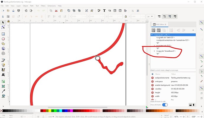
leads to a domain seller selling the domain. A search for the products doesn't turn up anything equivelent.

Peter
There are other cases where a common svg file across multiple parts is desirable. Many parts have the same standard PCB footprint. Those should be shared as well. There could be multiple files for a single footprint, for things like different pad sizes and shapes. BJT, MOSFET, op amp, are more cases where the schematic should be reused. I think there are many cases where existing parts have inappropriately created a new svg, where the only change is the addition of a part number. That can be done using a text label part in the sketch instead. The “schematic” tends to be the same for most “SPI” or “IIC” part modules. They do not really need unique svg files.

The existing documented naming convention supports this. The “description” portion of the file name can be as specific or generic as appropriate

It would also be “helpful” if a compatible footprint could be substituted in a sketch, without needed to create a complete duplicate part.

It is unfortunate that one of the common ‘fixes’ for the mess that Inkscape makes, is to to do mass, recursive ungroups. It would be nice to be able to «safely» put the connector id on a group for the non-circular pcb pads. That would allow tying the associated graphics together. I use an alternate cleanup process, that deletes “unused” groups (no attributes on the “g” element), and ids. It explicitly keeps any id that starts with “connect”.

A python script that processes svg files should not need the ids in order. The standard xml file handling tools should be able to collect all of the elements with “connect…” ids, and allow sorting and updating them regardless of where they are in the file. Renumber needs to be done simultaneously with the fzp file. Also across multiple parts, if the svg is shared.

Reusing existing svg files can conflict with the desire to have connection numbers both in increasing order, and matching the connection number in the fzp file. When the only difference for a part is the pin ordering, there is really no need for a new schematic. Just to reference the correct ids in the fzp file. The connectors can be in pin number order in the svg, but they might not match the connector numbers in the fzp.

The folder also shows what the layer is, or the (equivalent) prefix in fzpz files. It is common to use the breadboard view for the icon as well. I would not hurt anything to ‘duplicate’ that information with a suffix. I think the file naming convention already includes that.

Be very clear about that “tested Fritzing version”. Due to code changes over time, Fritzing handles some part details differently based on that version number. If you are making a new part from an existing part, certain things could break if the specified Fritzing version is changed. That said, a really old version number in a part probably means it «at least the new part» should be updated to something more modern, and following the more recent rules.

This is getting well outside the current topic of “Suggestions for additional documentation”.

That probably matches because “electrolytic” ends with “ic”. Agreed that it is a mess. Should have selectable options on what to search: «at least» family, description, tag, title, even label, and either sub string or full word matches.

Fritzing is used by a lot of DIY users. They could have a lot of parts on their workbench that you can no longer buy in stores. A possible alternative to deleting or obsoleting these:

– add a “status” tag with a value of “historical” or “nla”. Combine that with a way to filter the searches and bins by tag values (and save as a preference). Fritzing could default to only showing ‘active’ parts, but a simple toggle would allow those with an overflowing ‘junk box’ of parts to expand the list.

Just because “we” can not find a source does not mean that none exists.

A url in a part is a convenience, not a requirement. My usual preference for a url «if only one in a part» would be a datasheet, instead of a supplier. At least for anything reasonably generic.

I thing generic parts should be more common in core. Something that is usable to create a Fritzing sketch, that needs to have an ‘override’ specified for the part number. No ‘supplier’ url is is ‘correct’ for that.

A source for parts used in projects is a requirement to actually build it. Like the “nla” suggestion, a “no url” or “no source” flag could be used to filter these without deleting them.

Thanks, @vanepp !
Unfortunately, I have been very busy with exams and I could not take a look at this yet. And now I am going on holiday. I hope to look into this in July.

No hurry, it will get done when it gets done. I expect figuring out the questions raised is going to take even longer :slight_smile: .

Peter

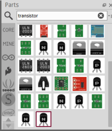
I agree with these comments. In addition, there are several parts duplicated as there are several parts where the only difference is a parameter. For example, search for transistor and there will appear several similar transistors where the only difference is the leg order (ECB, CBE, etc.)
image

I think the obsolete mechanism is just a way of having a newer version of a part. It is not related to the Life Cycle of the part. Maybe a field Life Cycle with Active, Not recommended for new designs, or End of life (obsolete) would be interesting. However, Fritzing tries to use “generic parts” and then we would need to tie the part to a specific part number. The URL in the part is, on several occasions, just a reference. So, difficult to implement and maintain for now…
Thus, I think I will leave the textile pots for now in the core and not obsolete them.

@vanepp , I will try to commit the changes to the repository this week. I reviewed the changes and have a few comments:

First, the moduleID of the potentiometers needs to end up in “PotentiometerModuleID”. This will create a part where you can change its properties (e.g., the knob_status, power, or maximum resistance). This will help to make the properties.xml file easier to maintain. For example, the maximum resistance property for the file is now like:

<property  name="maximum resistance" symbol="&#937;" minValue="0" maxValue="1000000000000" defaultValue="" numeric="yes" editable="yes">
	<suffix suffix="PotentiometerModuleID"/>
	<suffix suffix="alps-starter-pot9mm" />
	<suffix suffix="SparkFun-Electromechanical-TRIMPOT-3MM-2"/>
	<suffix suffix="SparkFun-Electromechanical-TRIMPOT--2"/>
	<suffix suffix="SparkFun-Electromechanical-TRIMPOT-TRIMPOT-5MM"/>
	<suffix suffix="SparkFun-Electromechanical-TRIMPOT-TRIMPOT_PTH_S3_LOCK"/>
	<suffix suffix="SparkFun-Electromechanical-TRIMPOT-SMD"/>
	<suffix suffix="SparkFun-Electromechanical-TRIMPOT--PTH-KNOB"/>
	<suffix suffix="SparkFun-Electromechanical-TRIMPOT-PTH"/>
	<suffix suffix="SparkFun-Electromechanical-TRIMPOT-3362U-2"/>
</property>

Ideally, it should like:

<property  name="maximum resistance" symbol="&#937;" minValue="0" maxValue="1000000000000" defaultValue="" numeric="yes" editable="yes">
	<suffix suffix="PotentiometerModuleID"/>
</property>

In your files, there are two potentiometer symbols for the schematics view: potentiometer_1_schematic.svg and pot-slider_5_schematic.svg, but they look identical. I think we should reuse potentiometer_1_schematic.svg file and avoid the pot-slider_5_schematic.svg. Or is there a specific reason for this?

Regarding file names, I tried to add a hash as the obsoleting script (which has several missing features, see here for the issue) does: fritzing-parts/obsolete.py at develop · fritzing/fritzing-parts · GitHub

In any case, I am ok with the names that you gave and I will leave them as they are. Maybe we should also use lower case for the files too. I will rename “Basic_Force_Sensing_Resistor_FSR_5_breadboard.svg” to “basic_force_sensing_Resistor_fsr_5_breadboard”.

Apart from that, your changes are ok for me. Thanks for your help!

Even better, but likely more code work, would be to have an optional attribute in the fzp file property attributes to make it editable in Inspector. As a base

<property name="voltage" editable="true"></property>

Extend that with the attributes currently used in the properties.xml file. Extend that again with an attribute to pull in a template from properties.xml (or elsewhere)

<property name="voltage" editable="true" rule="voltage" />
<property name="voltage" editable="true" choose="3.3,5" />
<property name="gain" editable="true" pattern="\d{1,4}(\.\d{1,3})?" />

The last (supposed to be) a regex pattern for a number that is either a number the is either an integer (up to 9999), or floating point value with up to 3 digits after the decimal point.

I’m currently working on an external parts factory (written in python) with the intent of suggesting that it replace the current parts factory code with a callable module (preferably user supplied callable modules that are included in the .fz file.) Then the interface to Inspector gets rewritten as an api that aims to interface to the callable modules (i.e. the code only supplies an api to interface to Inspector.) I currently have a male header (breadboard only so far) which is scalable and able to change color. Thus you supply the row, columns and pitch (and optionally a color) and it creates a header at that
pitch (with the rest of the part scaled to match that pitch.) To my mind that adds the required functionality, a python script gets the part maker access to Inspector which is very desirable. It would also enable changing hole sizes in parts (as the svg will get regenerated by the script.) Currently looks like this:

# set test parameters

part_type = "male-header"

rows = 8

columns = 2

pitch = "2.54"

pcb_type = "tht"

pad_type = "circle"

pin_order = "row"

color = "#404040"

moduleid = create_fzp(part_type, rows, columns, pitch, pcb_type)

svg = create_male_header_breadboard_svg(moduleid, part_type, rows,
                                        columns, pitch, pcb_type,
                                        pin_order, pad_type, color)

where pad_type will select a circle or oblong pcb pad once pcb is done. Currently the above generates this (a standard dual row 0.1in header which currently breadboard doesn’t do!) The row order parameter allows selecting sequential (row) where pins are

16 15 14 13 12 11 10 9
1 2 3 4 5 6 7 8

or column (with as many columns as you like) so a 3row 4column part would be numbered

3 6 9 12
2 5 8 11
1 4 7 10

or the more usual 2 column part

2 4 6
1 3 5

this is a svg of the 2.54mm 8 by 2 part above

1

.changing it to 1.27mm and color red gets this

# set test parameters

part_type = "male-header"

rows = 4

columns = 3

pitch = "1.27"

pcb_type = "tht"

pad_type = "circle"

pin_order = "row"

color = "#ff0000"

2

a 1.27mm pitch red header instead. So a single part provides any pitch you desire (pcb holes may be an issue for non standard pitch parts though!)

Peter

So the parts factory generates the properties to be used by Inspector. That is more powerful. A couple of items to note:

do not really want to write a plugin module if the only thing that is needed is to be able to set property values that do not affect the graphics

make sure that the plugins exposes the possible property names, so that inspector can switch from a non factory part in the same family, to a factory part based on the properties. Inspector needs to be able to show at least the property names for parts that have not yet been generated, if it is possible for a non-factory part to be in the same family. Or if there can be multiple factory plugin modules for the same family.

EDIT: EXTRA: the plugins would have to be included in the sketch files, to make them transportable. Just like custom parts are included.

Yes, I agree. Specially, that would be great for very specific properties of a part (that does not apply to a type of parts). Unfortunately, that is not how the code works right now.

Excellent! I looking forward to see it in action. Python is more accessible than C++ for a lot of people and bugs in the part factory would be easier to fix ans you do not have to check the rest of the code. Be sure to coordinate it with @KjellM .

Regarding the pots, I modified the slider pot to reuse the same schematic symbol as the others. As this pot has four pins, I made the second wiper “hybrid” in the schematic view. The file of the new pot is attached:
Slide Potentiometer.fzpz (6.8 KB)
. It would be great if you can spot any issues (I have not worked too much with hybrid connectors).

I committed the changes to my repository: GitHub - failiz/fritzing-parts at fix_simulator_issues However, there are some issues with a textile pot and it does not pass the CI test. The error is:
svg/core/icon/textile_strech_sensor_005.svg child element ‘style’ with no layer id
The file is just the same as the old one (the one that is in core in 0.9.10) but I just rename it. Any ideas about how to fix this error?

I figure on doing a standalone version that creates fzpz files (and since I’m using the pyside2 library to get at QT functions and thus have QT available, I may try a graphical version too :slight_smile: .) Once that is working (as it is useful on its own) then we can discuss integration. I can see a lot of issues and don’t know how easy it is going to be to get from the c++ code to python and back (the c++ code would need to provide the temp files for the .fzp and .svgs for instance that fritzing created and owns) and it may not work out. But with a working example rather than just hand waving, perhaps something will come of it. If not the standalone functionality is useful if less convenient (and likely quicker to produce than code changes to the parts factory!)

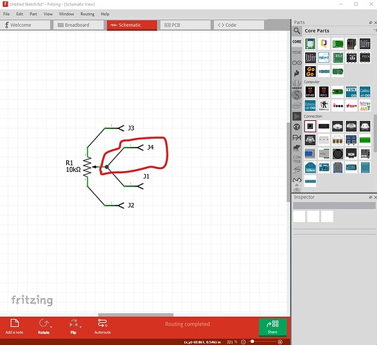
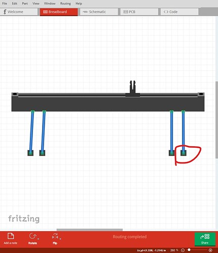
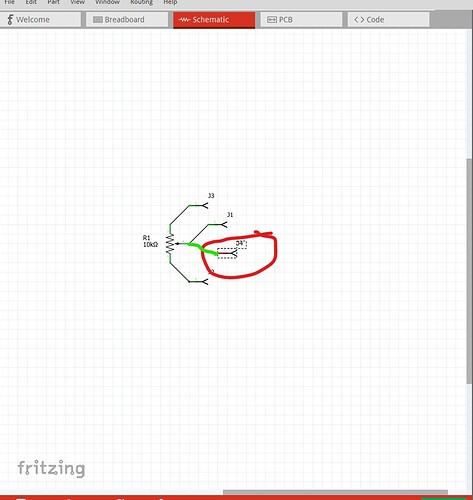
The slide pot looks fine, the hybrid doesn’t appear to be working however (possibly because of the bus):

j4 should appear floating (no connection because of the hybrid) but possibly because the two pins are bused together, it appears works correctly. I think I may have run in to this before on a bus. If you really don’t want it in schematic you can remove the connector definition in schematic in the fzp, but I think since the pin is available in both other views the way it works now is the correct answer. If you connect to both pins in breadboard or pcb it shows correctly in schamatic. I would probably remove the hybrid=“yes” in the fzp just in case this eventually gets fixed and then causes a problem in this part.

I don’t know on this one, but looking at Textile_potentiometer.svg in core parts I see its layerId is breadboard, I expect the complaint is because the layerId isn’t icon to match the .fzp file. I’d try changing the layerId to icon in the icon svg and see if that makes CI happy.

the core part was probably in place before CI was added and thus hasn’t been caught because it hasn’t changed.

Peter

I did not follow your explanation. However, after more testing I detected that it was not working properly. It worked well in the sch view you drag a connector from one of the legs of the pot to one component, but no when you draw the connection from another component to the connectors of the pot. In that case, all the pot was attaching to the second wiper (which should have been hidden in the sch).

So, I modified the FPZ file of the slider pot to remove the second wiper from the sch view. Now it looks like:

<connector id="connector3" name="wiper-1" type="male">
      <description>second wiper connection</description>
      <views>
        <breadboardView>
          <p layer="breadboard" svgId="connector3pin"/>
        </breadboardView>
        <schematicView>
        </schematicView>
        <pcbView>
          <p layer="copper0" svgId="connector3pin"/>
          <p layer="copper1" svgId="connector3pin"/>
        </pcbView>
      </views>
    </connector>

This is the new slider and seems to work properly:
Slide Potentiometer_without_hybrid_connector.fzpz (6.8 KB)
If you could test it too, it would be great.

Yes, that made the trick. The stretch sensor and the analog pressure had also similar issues. But now, all of them pass the CI tests. Thanks for your help!

Actually I prefer the first version (except as noted with the hybrid=“yes” removed.) This version leaves a connection to the wiper unconnected in schematic when in fact it is connected. My original probably wasn’t clear due to the lack of breadboard corrected here:

the second wiper connection circled in red doesn’t connect in schematic (when it did in the original version)

the connection in green should be in schematic as it actually exists I think. J4 is missing its connection to the wiper in schematic but is there in breadboard and pcb.

Peter