To change schematic you need to use an svg editor such as Inkscape. To do that you need to unzip the .fzpz file which will give you a file called
svg.schematic.sim900-generic_1_schematic.svg
which looks like this in Inkscape:
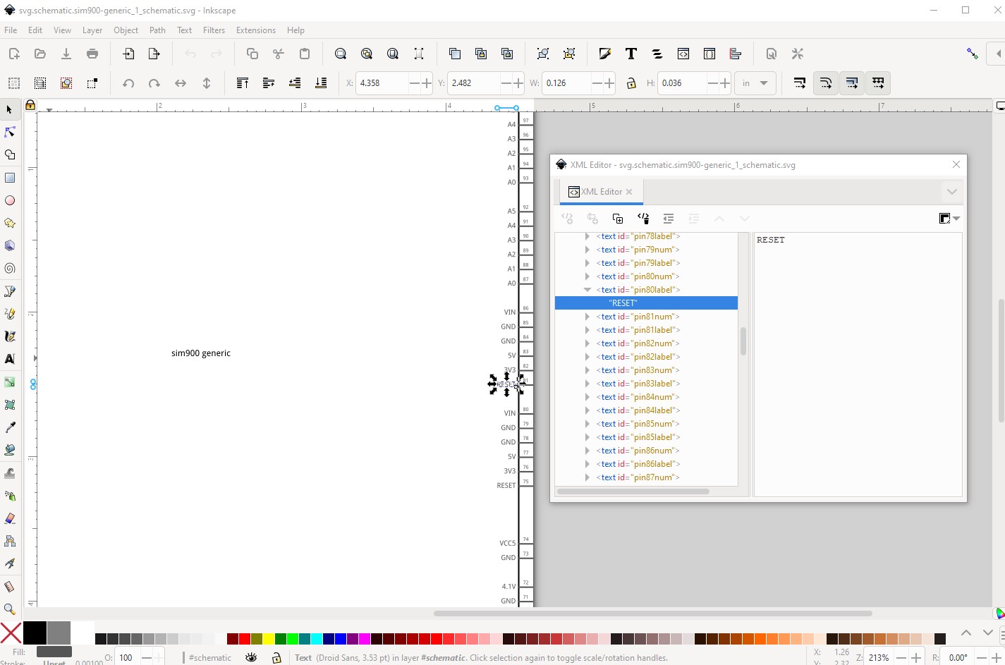
Here I have selected the RESET pin name and it is changeable in xml editor on the right. If you aren’t familiar with Inkscape it may be easier to let me make the changes (you also need to run the part through FritzingCheckPart.py to clean up some Inkscape features that are incompatible with Fritzing.) If you like instructions are here (although it is complex!) in the tutorials section of the forums:
or you can upload the .fzpz file that Parts editor made (upload is 7th icon from the left in the reply menu) and I can make the necessary changes from the fzp file. As well do you have pin names for the 3 connectors on the top of the board?
Peter