Hello,
I search the fritzing files for my screw terminal shield. I have used Google for about 3 hours but no hit. I found a lot of shields but not this.
Hello,
I search the fritzing files for my screw terminal shield. I have used Google for about 3 hours but no hit. I found a lot of shields but not this.
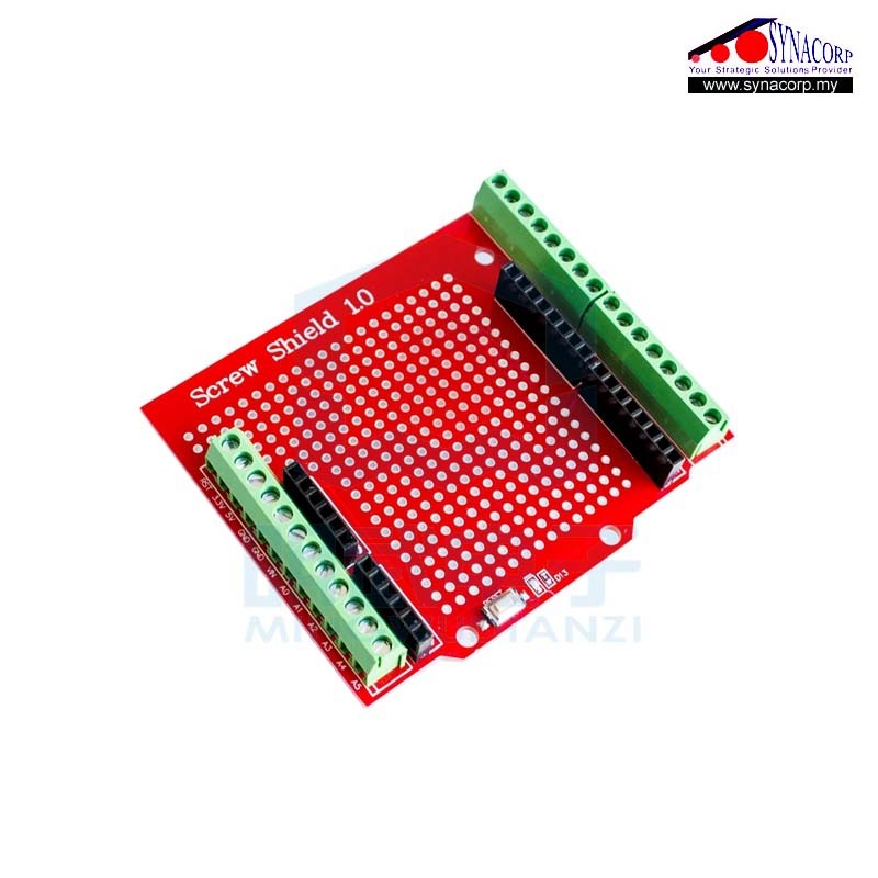
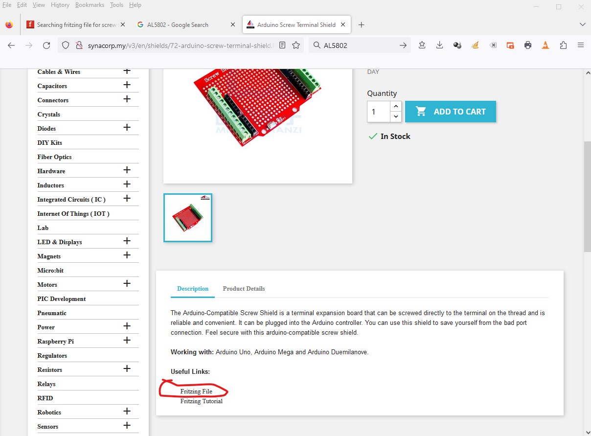
There doesn’t seem to be a part and there isn’t enough information here to make a part (or that I can find on the net either!) I assume the screw terminals (for which we need the pin pitch, they look like 0.156 pitch) connect to the Arduino pins but I would expect them to also come out to a set of proto pads (which aren’t documented.) Although a look at the web site for the part indicates there may be a Fritzing part available (it wants me to sign in to google which may or may not give me access to the part but it may work for you!) Click on the link circled in red in this image and see if you can download the part.
Peter
Hell,
thank you.
The pitch of the screwterminals is 3,5mm.
Available for example at “Phoenix Contact” and many others.
I followed the link and found a lot of files there. But no one for this shield ![]()
Wolfgang
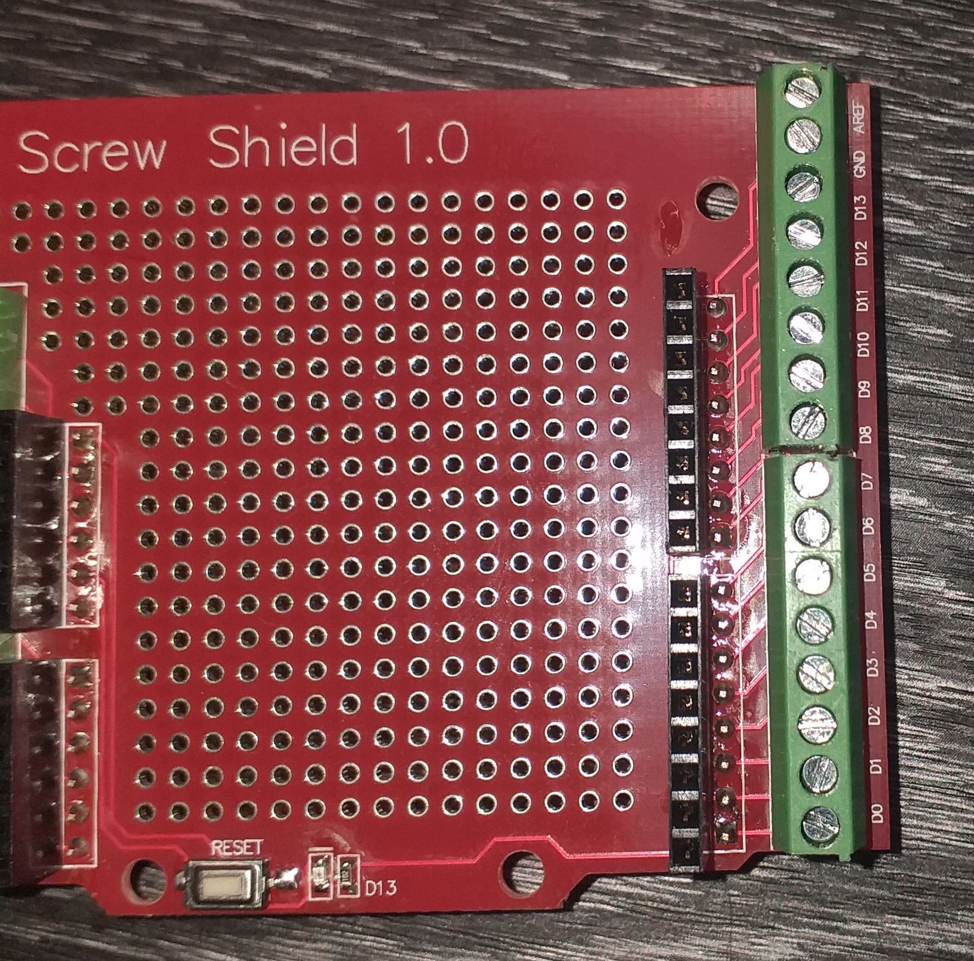
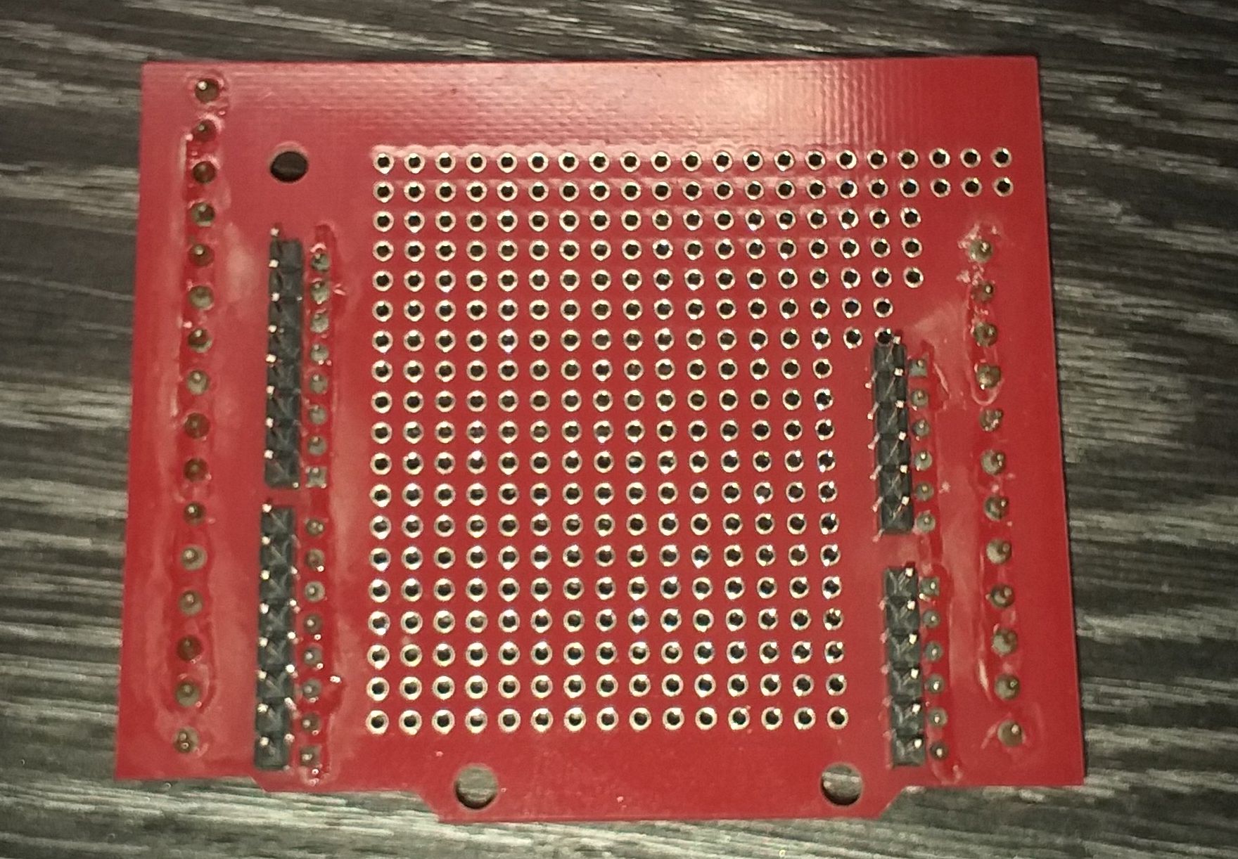
Still need the connections (only to the Arduino pins or to pads as well? Am I correct the Arduino pins go to the screw terminals?) from the screw terminals to make a part. None of the pictures I have found have that kind of detail and it is needed to make a part. The physical layout should be obvious enough from an Arduino outline (and one of the jpeg images. )
edit
as an example this proto shield I recently did for someone has the connections that I am referring to (which I am assuming exist in your board, but are not documented anywhere I can find.)
Here they are implemented as traces between the arduino pins and the pads. I need a similar list for the board you have (which may be as simple as a straight on photo of both sides of the board showing how the traces connect between the screw terminals, the arduino pins and potentially the pads.)
Peter
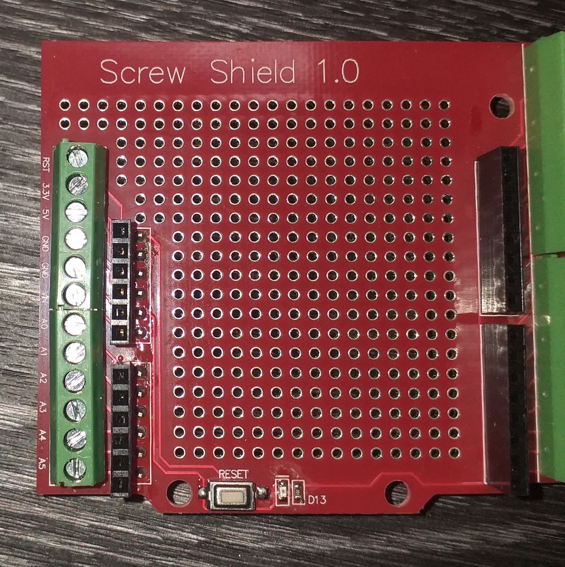
The screwterminals are 1:1 to the Arduino pins.
All holes are not conneceted.
The reset-switch is: left pin/pad to GND and right pin/pad to RST
The left pin of LED is GND
The right pin of LED is to bottom of R
The top pin of R goes to D13.
Looks good. I’ll work on a part …
Peter
Despite how it appears, I haven’t forgotten you ![]() I am using a new Inkscape extension that I found to adjust the perspective of your image to get it flat. That is taking me some time to get right.
I am using a new Inkscape extension that I found to adjust the perspective of your image to get it flat. That is taking me some time to get right.
Peter
Hello,
very great! Thank you.
Wolfgang