Hi, hope anyone already used this TFT display.
I’m searching for the corresponding part with the SPI interface (8 pins).
Many thanks.
Hi, did you find a display part. I so could you pls send me a file that I need for my fritzing project
Thanks a lot in advance
MrMind
I’ve seen the part in JPG captures of other Fritzing projects… but I’ve never seen the part for this display itself.
Did anyone ever create this part and upload to an archive here or on Github?
Can anyone provide a link here…?
Thanks
Mike
(1st post)
Did you search Google. Follow those images and look for .fzpz or .fzz or .fzb. It could also be a part in someone’s big bin, like Adafruit.
Do you have link to a datasheet so we can see how hard it is to make.
From a google search with the term “fritzing part st7735b” it appears to be in the adafruit fritzing library on github. That library isn’t loaded in to fritzing by default you need to download the bin from github and load it in to fritzing.
Peter
Thank you both for replying so quickly!
A part for a 1.8" display is in the Adafruit library… but it’s not the same screen as the one I have.
For future seekers, here’s a direct link: https://github.com/adafruit/Fritzing-Library
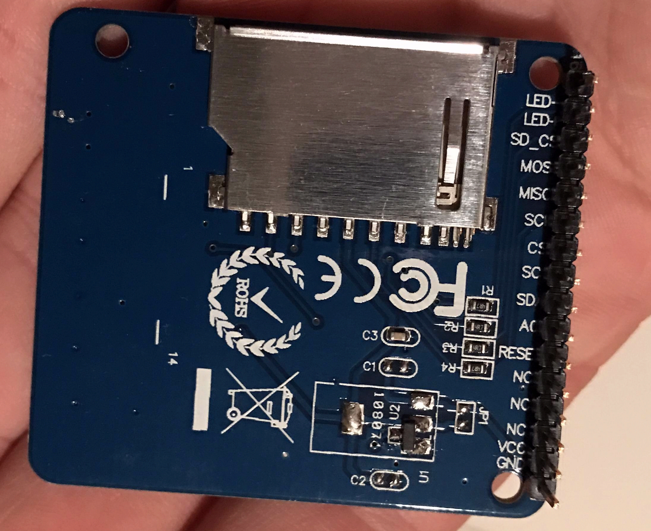
Here’s a photo and image showing pin count - as you can see, it’s NOT the same as the Adafruit model:

I will look for a datasheet next…
Mike
That’s too much searching for me.
Basically we need to know exactly what part it is and if there is a similar FZ part we can modify, and that is too many parts for me to open up and see what they look like.
Post links when you find them.
I’m mostly finished a modification of the adafruit part to convert it to this. I’m done for tonite and busy tomorrow but a part should be along soon (only pcb and the fzp file to finish). I found board dimensions (if not hole nor header placement which are just guesses) on ebay so it won’t be quite correct unless you can measure the placement of the holes and the pins with calipers but it should do the job. The adafruit part looks to be the alternate layout for this same display (only 10 pins instead of 16, different mounting holes and board size).
edit: This part should do what you need. Note that breadboard and pcb positions are a guess from the photos online as I can’t see a mechanical drawing anywhere so if you need accurate mounting holes you would need to measure a real board and adjust the part to match. One other late thought: if you are using this on a 5V system you need level translators such as the 74ahc367 or 74ahc541 (both available in parts submit) to translate the 5V levels to 3.3V. Despite what the ebay post says these devices are not 5V tolerant, they want 3.3v VCC and 3.3v signal levels.
kmr1_8_spi_tft.fzpz (8.2 KB)
Peter
1 Like
Thank you for making the part. I was looking for a copy of whatever had already been made.
if you need accurate mounting holes you would need to measure a real board and adjust the part to match
Yes, the pins should align with a standard breadboard. I’m not sure how to fix this. But again, I was looking for a copy of something that already existed out there somewhere. If making a new part is the next best thing, I’d need help to know how to “resize” this part to allow it to plug into a breadboard to be able to use it.
Thanks again
Mike
The header pins are fine. They are standard .1 spacing and will fit breadboard just fine. They may not be in the correct place relative to the edge of the board because there is no data on where that should be, and the 3 mounting holes in the pcb are probably in the slightly wrong place and wrong size because again there is no data on where they should be or what size they should be. This is only important if you are making a pcb and need the mounting holes and connector pin locations to be accurate (the mounting holes if you are using them you would need to be accurate, but you can drag a hole in to the pcb view from the parts bin and set the holes where ever you like. This part should be functionally identical to the original (that doesn’t appear to be available) as far as Fritzing is concerned.
Peter
I guess I still have a few things to learn about using Fritzing interface. I just reloaded this part and it lined up perfectly with the breadboard parts.
Thank you again for making this. I’ll try to learn more about how to do that someday. For now, I’m off making a schematic and layout with my new part.
Thank you again,
Mike
Ah, you were likely bitten by one of the bugs in Fritzing. It sometimes doesn’t align parts on the grid until you move them and then they snap to the grid correctly. Another is if you drag the part in to breadboard view often the schematic view is rotated by 90 degrees one way or the other. If you drag the part in to schematic view it seems to be correctly aligned every time I’ve seen so far (come to think of it I haven’t checked what breadboard looks like though). Both of these are on my list of bugs to try and fix when I get better at development (however neither may be easy to fix without a lot more knowledge).
Peter
Anyone done this display ?
It is very similar to the AdaFruit 2.0 except that it is 8 instead of 9 pins and slightly smaller.
I tried editing the AdaFruit 2.0 but I am clueless with the parts editor

There doesn’t seem to be one, but because (at least for me) it is an easy mod this should do what you need. As always if you are making a PCB you need to check the footprint (the mechanical drawing I found online isn’t all that complete and the 4 pin header may not be aligned quite correctly). Note to use the SD card you need to populate the 4 pin header (as the SD card doesn’t seem to connect to the 8 pins for the display).
TFT 1.8 inch 160x128 w SD.fzpz (8.7 KB)
Here us a copy of bb view so others can see if their card matches without downloading the part:

Peter
2 Likes
Thank you.
I wish editing parts was as easy for me.
Trying to mod the closest AdaFruit Part proved disaterous.
BTW there are several TFT’s with this footprint or one very close.
One thing people should be careful of is whether they have a 5v or 3.3v board.
Or on that can do either.
The image looks correct.
I will try to check the 4 pin SD header - though I do not use that header myself.
I like this part because it is cheap easy to program and can be used for most any device that supports SPI.
I would prefer it did NOT have the SDcard. but the displays without it are more expensive.
Again thanks.
Thank you Peter for providing us this fzpz 
Maybe you can add the pin descripions from the backside of the display
as VCC GND CS RESET A0SDA Sck and LED
As I’m a newbee I’m dare to do it by myself
All the best
The normal Fritzing convention is to make breadboard look like the actual part, so the printing on the bottom won’t be visible. However if you hover over the pin with the mouse the description for the pin will come up like this:

which has the same effect with a little more work.
edit: That said the change is easy so here is a new part with pin labels added:
TFT 1.8 inch 160x128 w SD pin labels.fzpz (7.2 KB)
Peter
2 Likes
Hi vannep, would you allow me to use the fritzing part for that display in a book?
I’ll surely give credits for that 
Edit: I’m like to use it for in one: https://github.com/PacktPublishing/Programming-Microcontrollers-and-WebAssembly-with-TinyGo
Go for it! I make parts because if is fun and have no objection to folks using them for whatever they like. Pointing folks at Frtizing as being a good way to document their projects would be appreciated as well, Fritzing needs more users!
Peter
2 Likes