Thank u very much! That saves me a lot of time 
Every project in this book has several images taken of fritzing giving credit to fritzing everytime. That already is a good amount of pointing towards this software
Thank u very much! That saves me a lot of time
Every project in this book has several images taken of fritzing giving credit to fritzing everytime. That already is a good amount of pointing towards this software
Hello Peter,
Many thanks for your hard work with all the parts!
I don’t manage to remove the left part as my screen does not have the sd_… (the header?). How is it done in fritzing?
Unfortunately to remove connections you need to make a new part. Easy for me, probably less so for you, so here is a new part without the SD pins.
TFT-1.8-inch-160x128-no-SD-pin-labels.fzpz (6.2 KB)
Peter
That’s great, thank you Peter!
Hi, I’m looking for a part that is very similar to
https://forum.fritzing.org/uploads/short-url/5ICHE12aSo3BD9NINASOkDgS7R5.fzpz
(The “TFT 1.8 inch 160x128 w SD pin labels.fzpz” shared above.)
It is a 1.8 inch ST7735S SKU:MAR1801 - 128x160 TFT. It has 11 pins on a yellow header and different pin layout. The details can be found at
http://www.lcdwiki.com/1.8inch_Arduino_SPI_Module_ST7735S_SKU:MAR1801
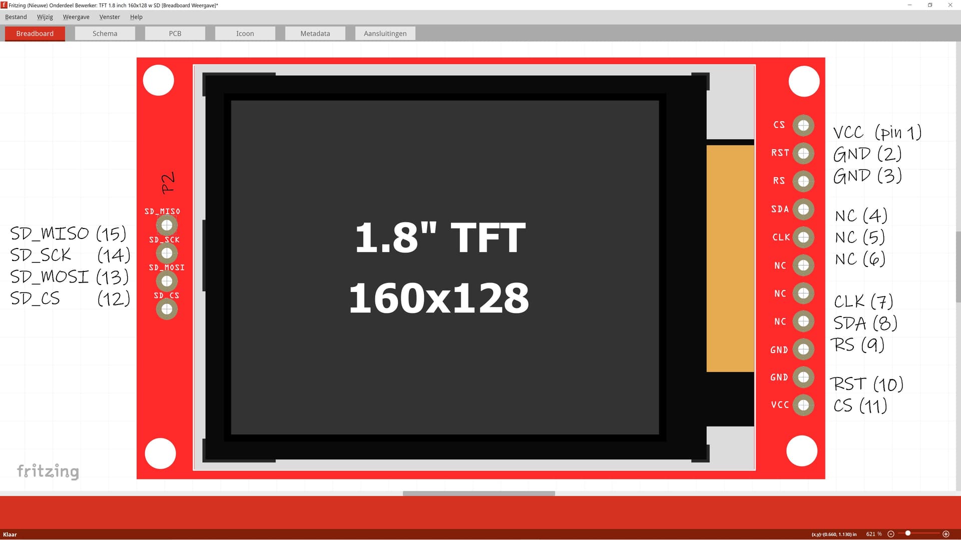
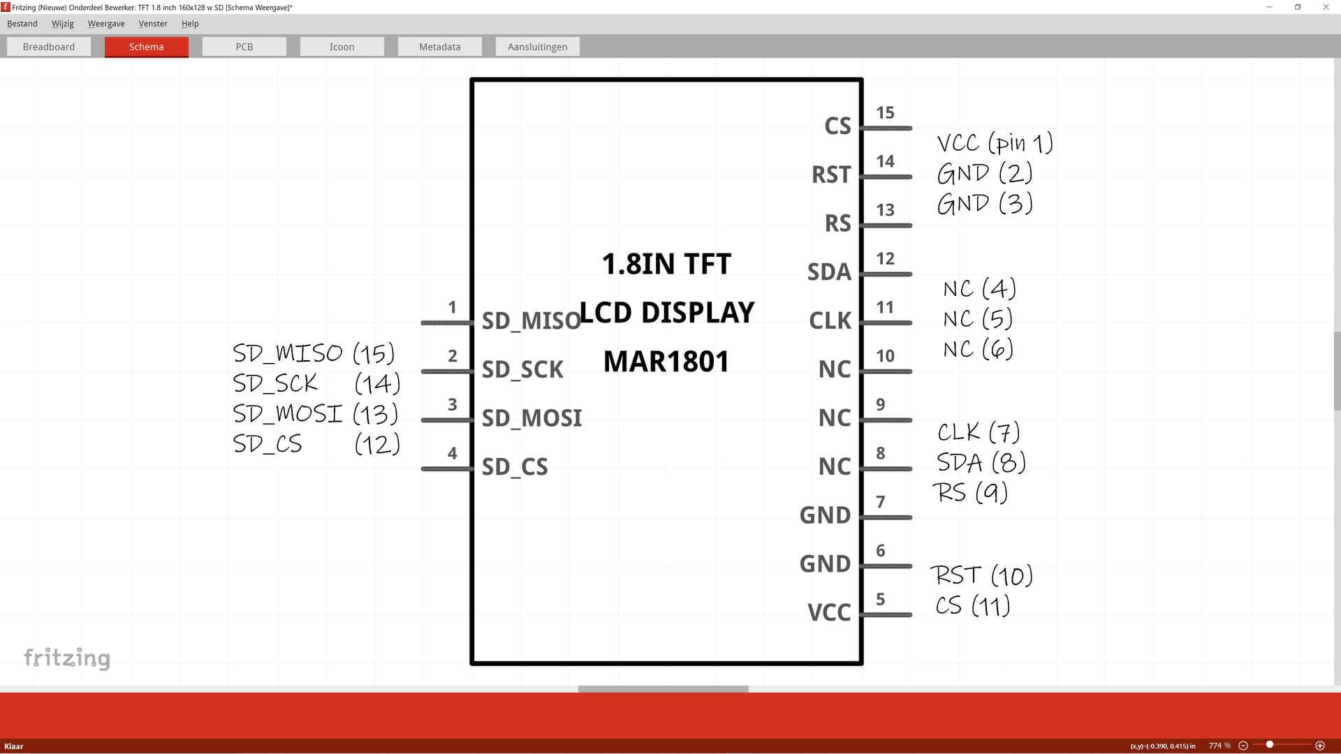
Hoping someone has made this part before? The pin layout (found in the manual link on the page mentioned above):
SPI on TFT / Card Reader: 1.8 inch Arduino SPI Module ST7735S SKU:MAR1801
Source: Page 2 and 3 on www.lcdwiki.com/res/MAR1801/1.8inch_Arduino_SPI_Module_MAR1801_User_Manual_EN.pdf

Number Module Pin      Pin Description
1      VCC             LCD power supply positive pin (3.3V~5V)
2      GND             LCD Power ground pin pin
3      GND             LCD Power ground pin pin
4      NC              Not defined, reserved
5      NC              Not defined, reserved
6      NC              Not defined, reserved
7      CLK             LCD SPI bus clock pin
8      SDA             LCD SPI bus write data pin
9      RS              LCD data / command selection control pin (low level: command; high level: data)
10     RST             LCD reset control pin (reset at low level)
11     CS              LCD chip select control pin (enabled at low level)
12     SD_CS           SD card SPI bus chip select pin (SD card function expansion application)
13     SD_MOSI         SD card SPI bus write data pin (SD card function extension application)
14     SD_SCK          SD card SPI bus clock pin (SD card function expansion application)
15     SD_MISO         SD card SPI bus read data pin (SD card function expansion application
This part should do what you want.
edit: replaced part with a corrected version. Note you will need to delete the current part in your mine parts bin and restart Fritzing in order to be able to load the new one.
TFT 1.8inch_Arduino_SPI_Module_ST7735S_SKUMAR1801.fzpz (6.9 KB)
Peter
Excellent! Thank you! That is what I was looking for.
Not that I need it fixed, but for completeness sake: there are a few minor issues where it deviates from the real world:
Update:
In addition what was mentioned above, I just noticed that the view of the part is the top view, but the naming order of the pins is from the bottom view. This does make the part hard to use as the pins are in the wrong order. I believe this is the correct pin layout for a top view of the part. I know it is a lot to ask, but can this be updated? It would also apply to the Icon view.
The same changes are needed for the Schema view, I guess?
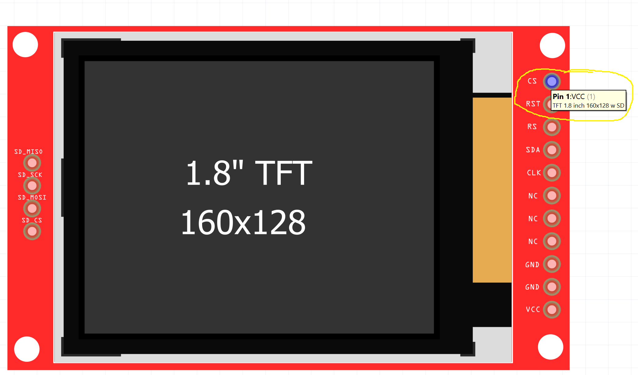
OK. Tried to change the part myself with the new parts editor. First I changed the pin descriptions in the Connections tab. Then in the Breadboard view and Schema view, I was able to assign the images to the correct pins. Now, when I hover over the pins, the pop-up shows the correct pin number.
But the text near the pins is still invalid. Not sure (yet) how that can be changed. But at least for now, I have a somewhat workable part.
Cosmetic error (fixed anyway!), missed one fill:#ffffff which should be fill:none.
The only information is images on their site and the images are from bottom view. I tried to convert to top view but obviously got it wrong. I will replace the part with a corrected one.
Peter
Thank you so much for your help! The updated part is exactly what I need.
Hello Mike.
I hope it is better late than never.
Wanted a more accurate representation for my project’s fritzing diagram (it’s just a me thing).
And here we are.

KMR 1.8 128*160 TFT SPI Fritzing File
EDIT: above is only the plain svg file. Here is the fritzing part. Underlying PCB and connections are preserved as made by @vanepp, only the graphics/visuals have been updated.
TFT 1.8 inch 160x128 w microSDRev2.fzpz (20.0 KB)
Cheers.
UPDATE: This part as for now is only fine for visual works and representations, not fully implemented as a functioning fritzing part, as rightfully pointed out by the verification kindly done by @vanepp.
While I will be slowly working on it, if anyone else wants to seriously work on this design and part, here is the link to the topic thread where @vanepp guides (me) through the starting processes involved and the fundamentals beyond adding the graphics and making it a fully fritzing integrated part.
KMR 1.8 128*160 TFT SPI Fritzing File
Cheers.