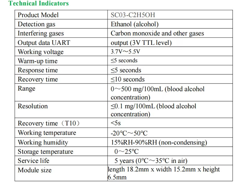
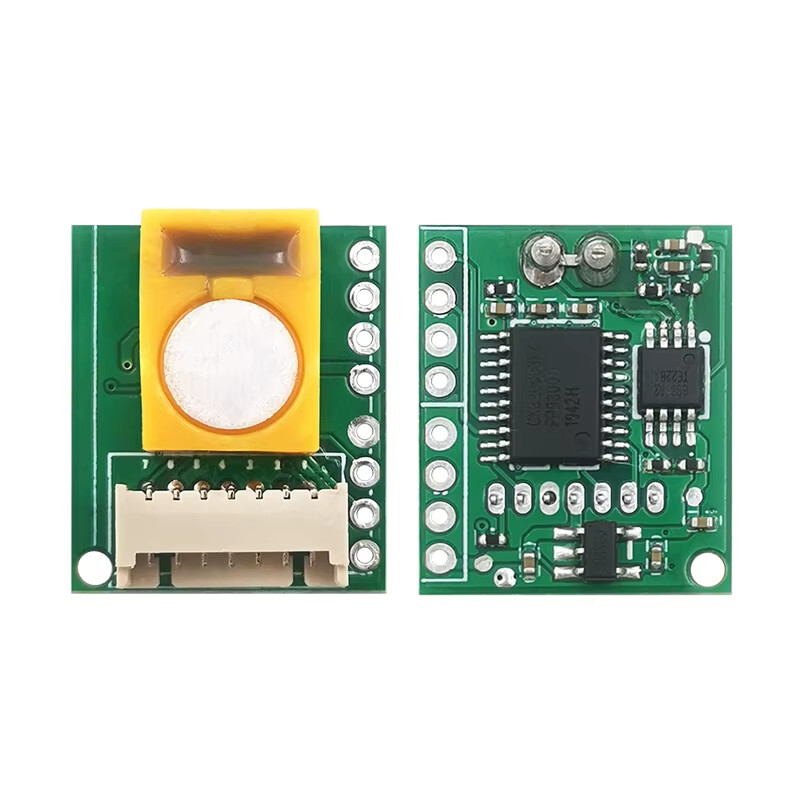
SC03-C2H5OH electrochemical ethanol module is a general-purpose, miniaturized module. Using the electrochemical principle to detect C2H5OH existing in the air has good selectivity and stability. SC03-C2H5OH is a general purpose gas module designed and manufactured by combining mature electrochemical detection technology with sophisticated circuit design. It has digital output and analog voltage output, and is suitable for various application circuit schemes.
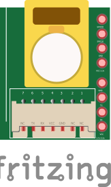
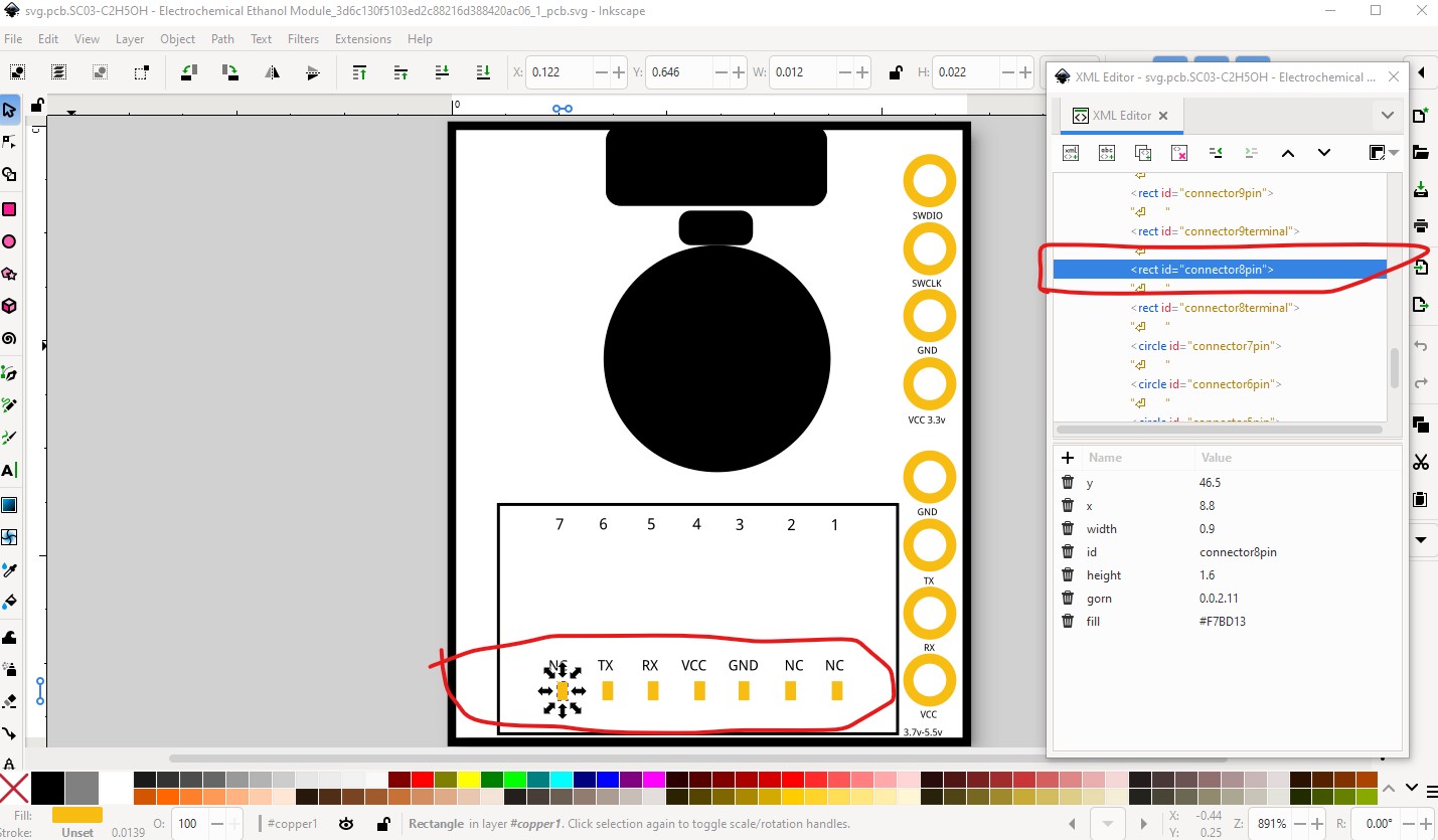
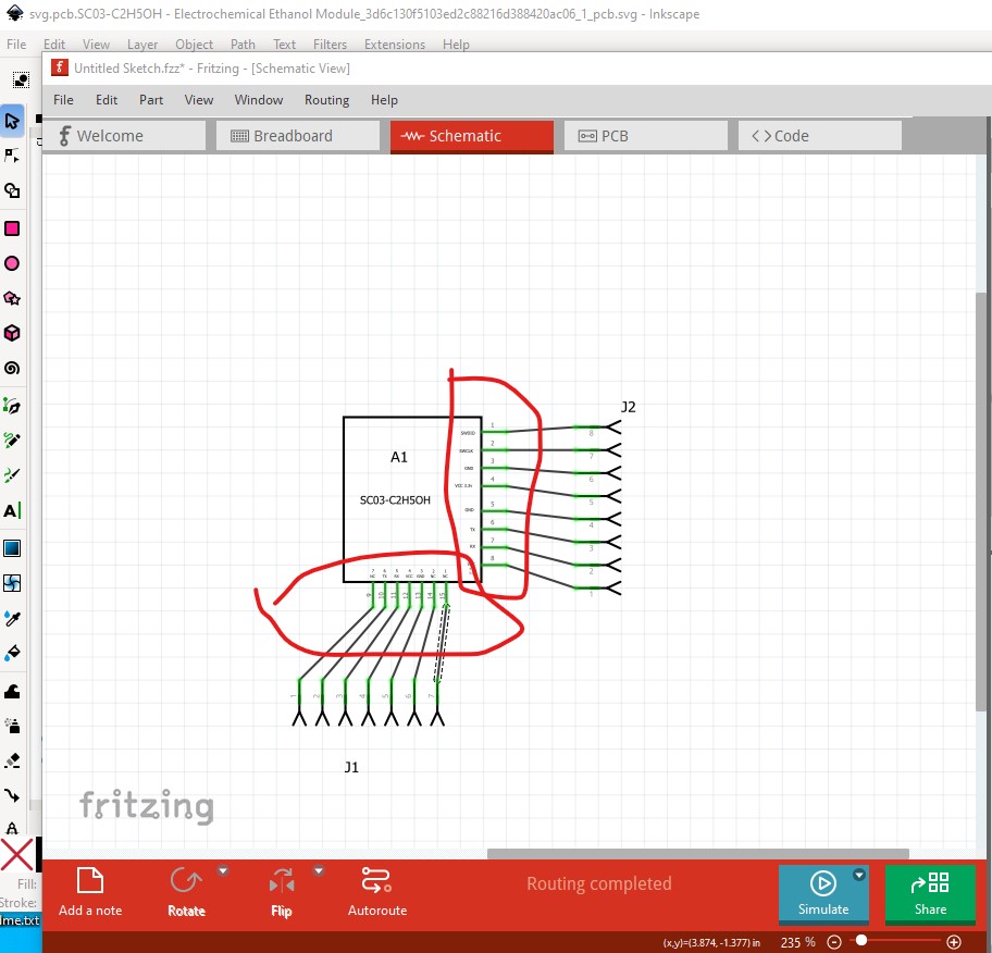
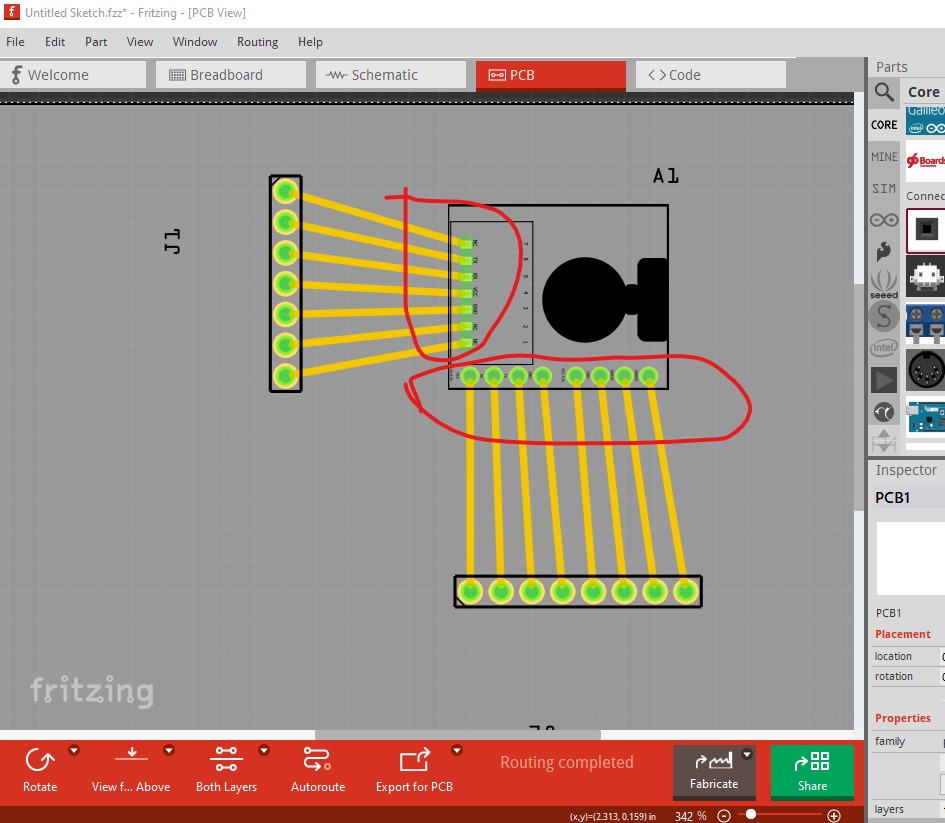
The connector which appears to be SMD should be suppressed in pcb as it isn’t through hole as the pads are and thus won’t work there. Schematic is not aligned to the 0.1in grid which it should be (the easy way to do that is to use Randy’s Inkscape schematic extension.)
It is likely the through hole connectors should be on 0.1in centers like the header connected to them and as noted the SMD connector shouldn’t appear in pcb.
If you wish to fix this up for yourself this tutorial will likely give you the necessary information (as well as were to get a copy of FritzingCheckPart.py and Randy’ Inkscape extension):
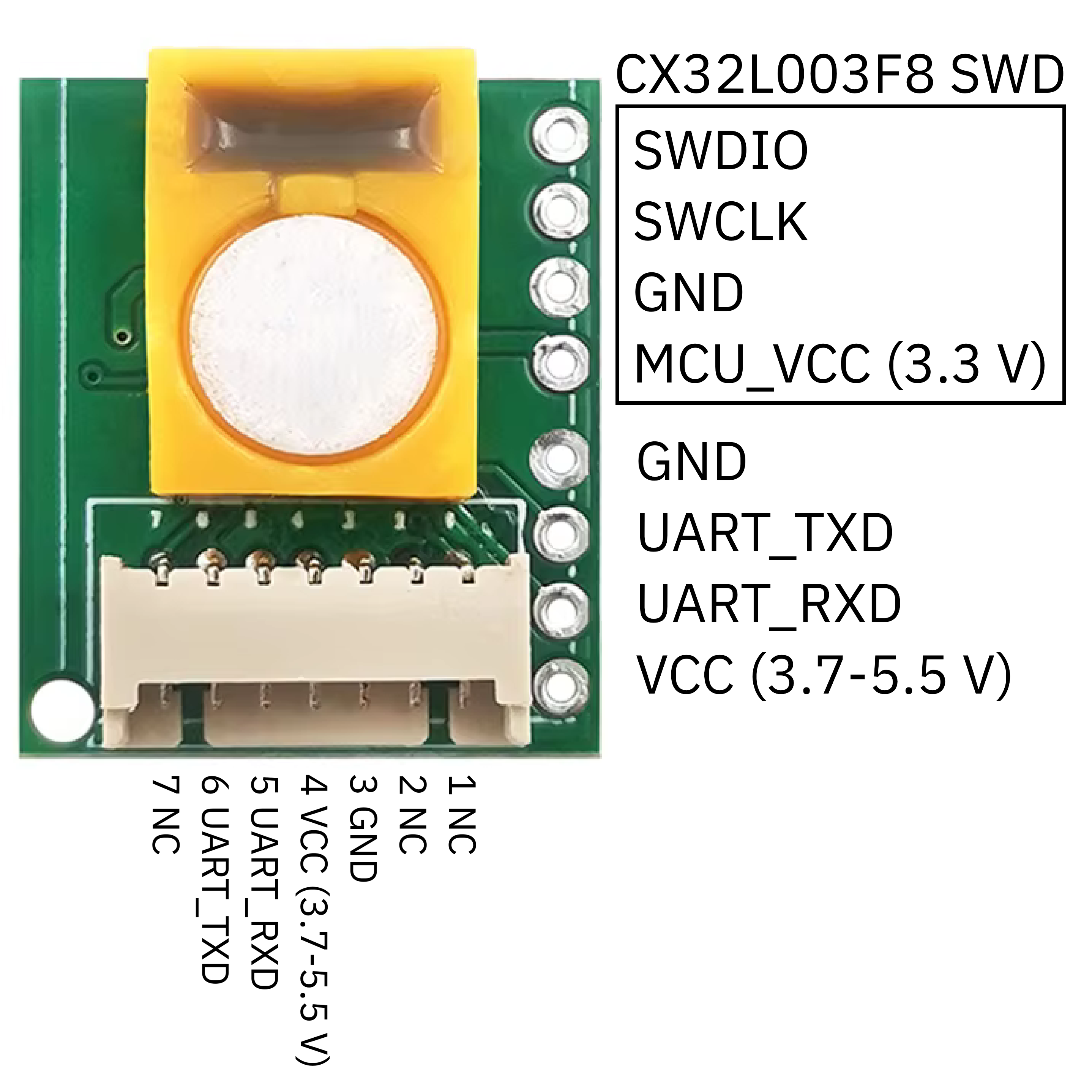
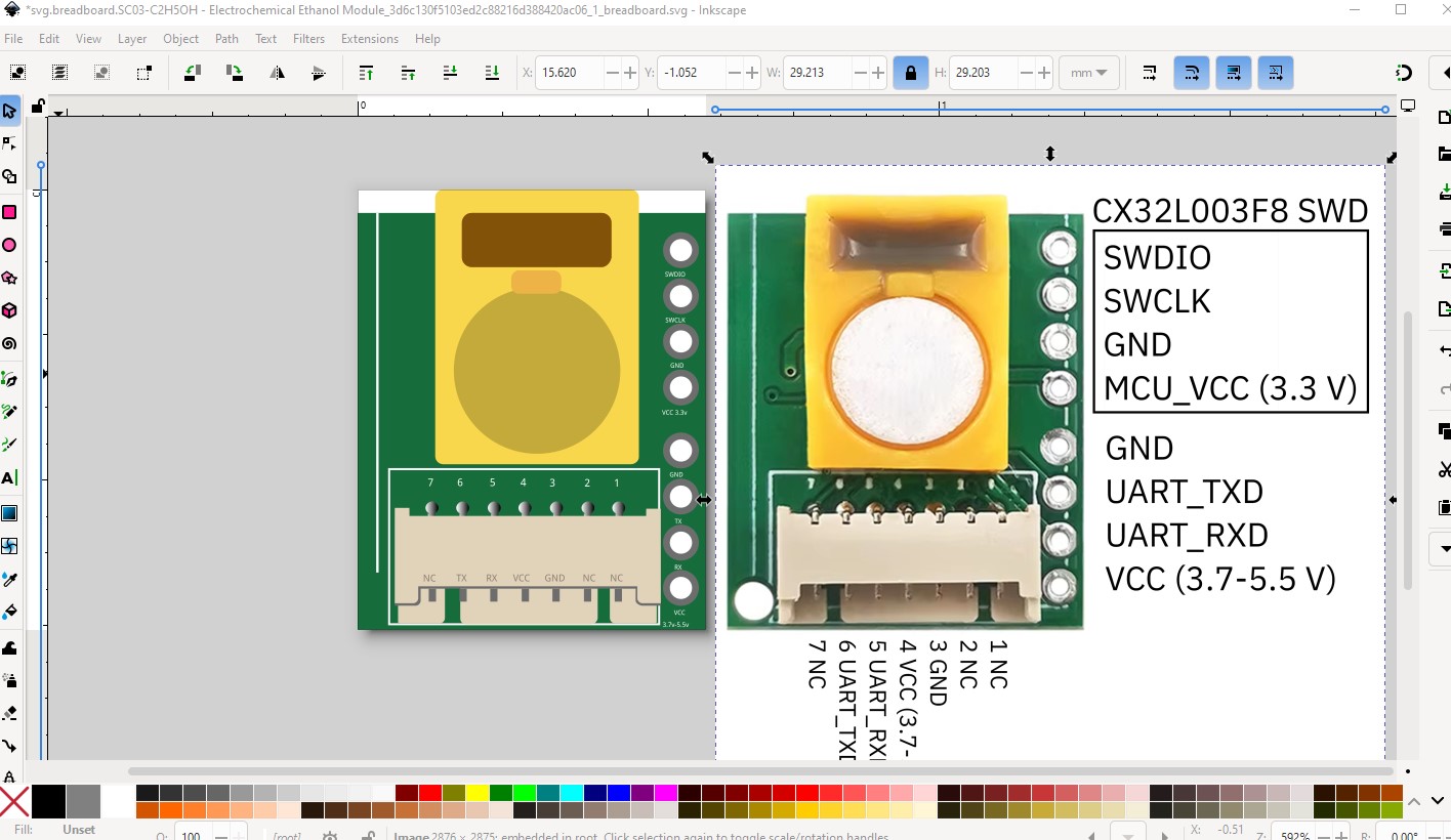
OK here is a fixed up part and what I did to it to fix it up. Starting with breadboard. Loaded the breadboard svg in to Inkscape then imported the jpeg image of the board (after deleting the images in the svg, in general images are undesirable as they won’t scale as a svg image will) and scaling it to match the size of the actual part.
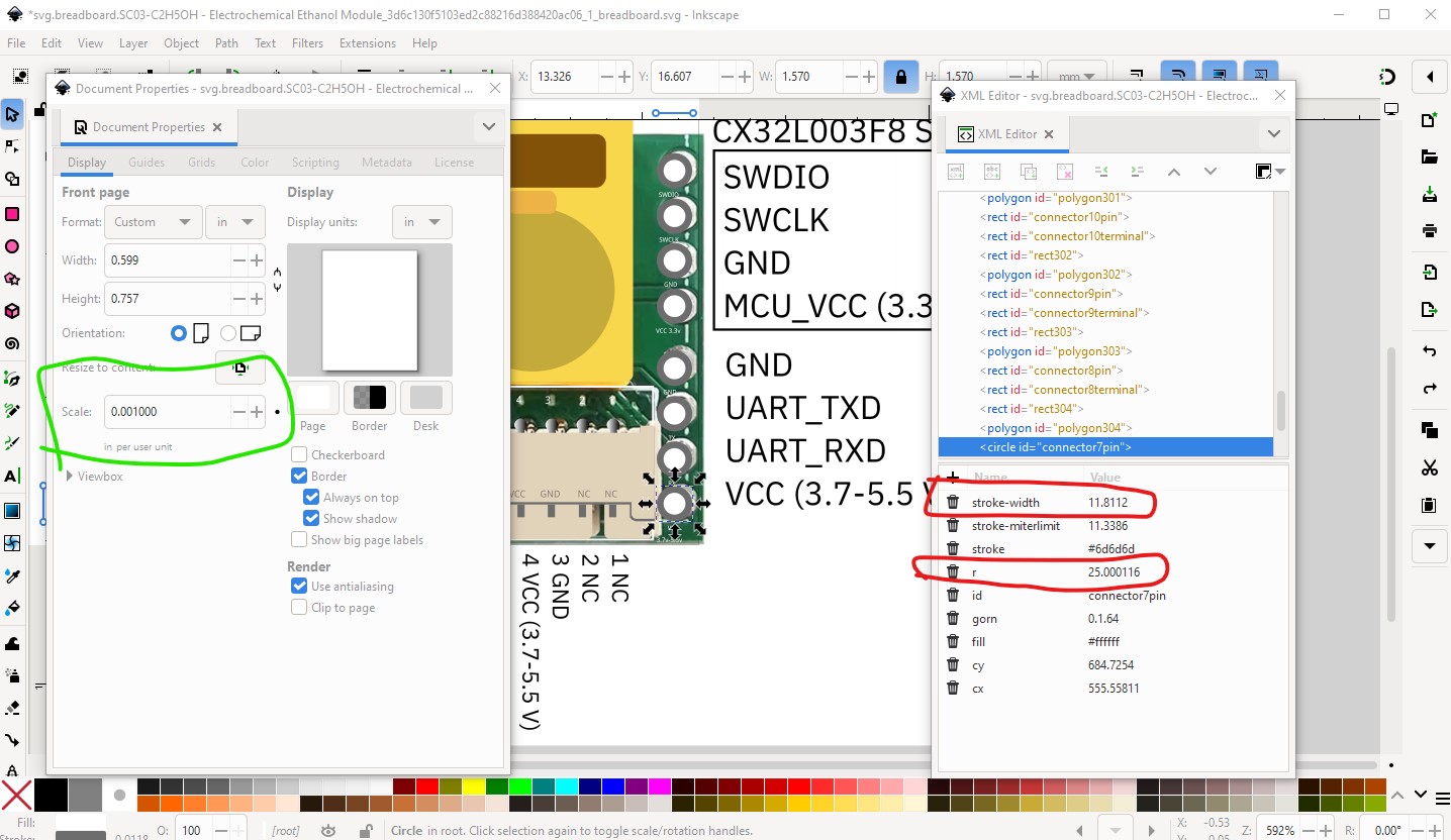
Then moved the base rectangle to below the image so the base disappears but the elements are above the image and will appear on top of it. I rescaled the image (which I’m not sure is possible in Illustrator which you appear to be using) to match the desired Fritzing value of one drawing unit being 1/1000th inch.
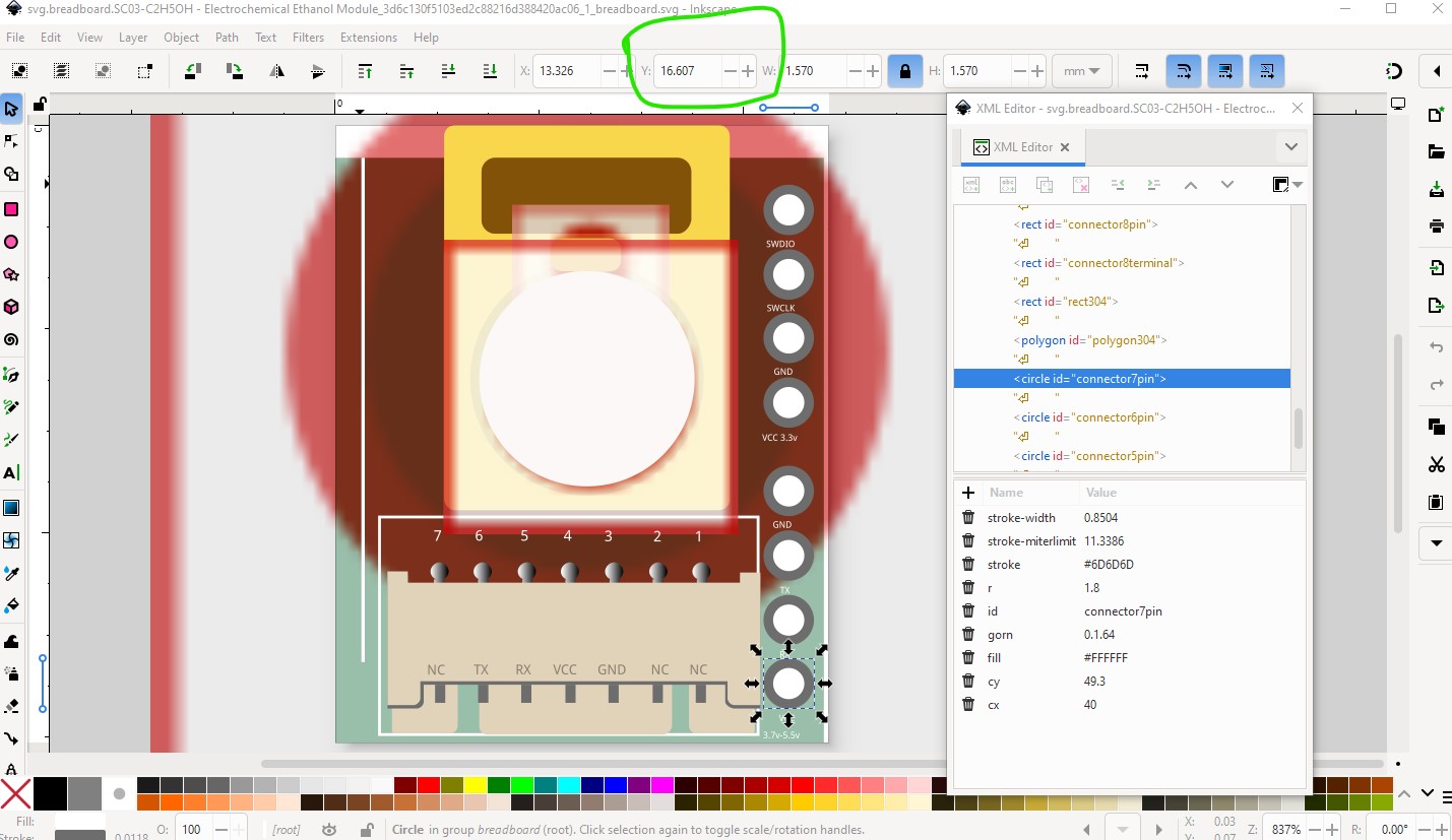
The image is pulled down a bit but aligned in X to the base so we see the connector and the pads need to move right in X to be in the correct place and so the connector clears the mounting hole on the left (which should be in breadboard!)
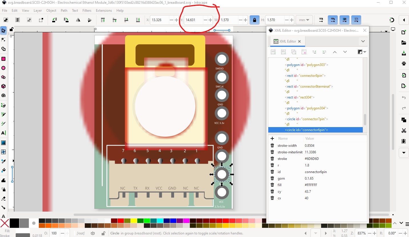
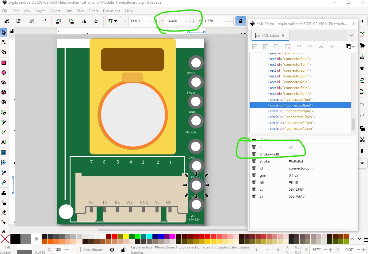
As well the hole is 0.0382in (which is fine for a 0.1in header, but too large for a 2mm connector) so we need to reduce the stroke-width and radius of the pads to match a 2mm header.
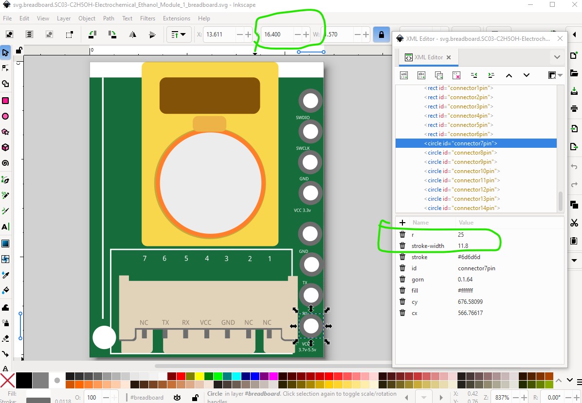
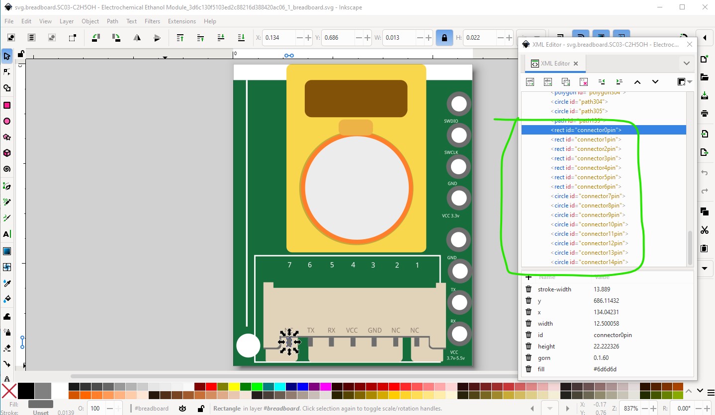
Then we want to move the connectors to the bottom of the svg and in to the order that Fritzing expects them (connector on the left top if there was a connector there, in this case on the left bottom) and going up from there. I have tools which will renumber pins if the svg is in this format which is why I did this rather than manually renumber the pins.
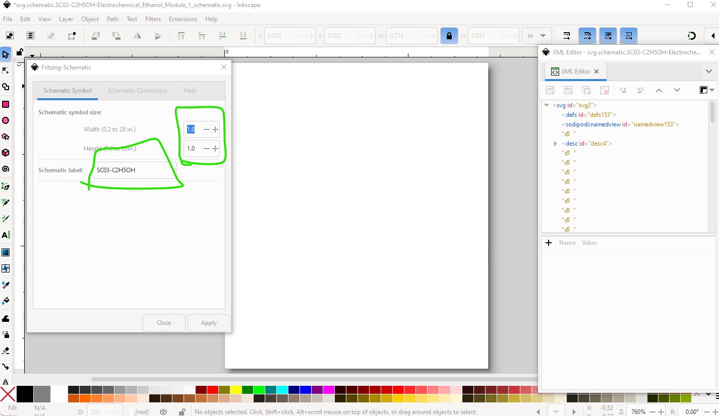
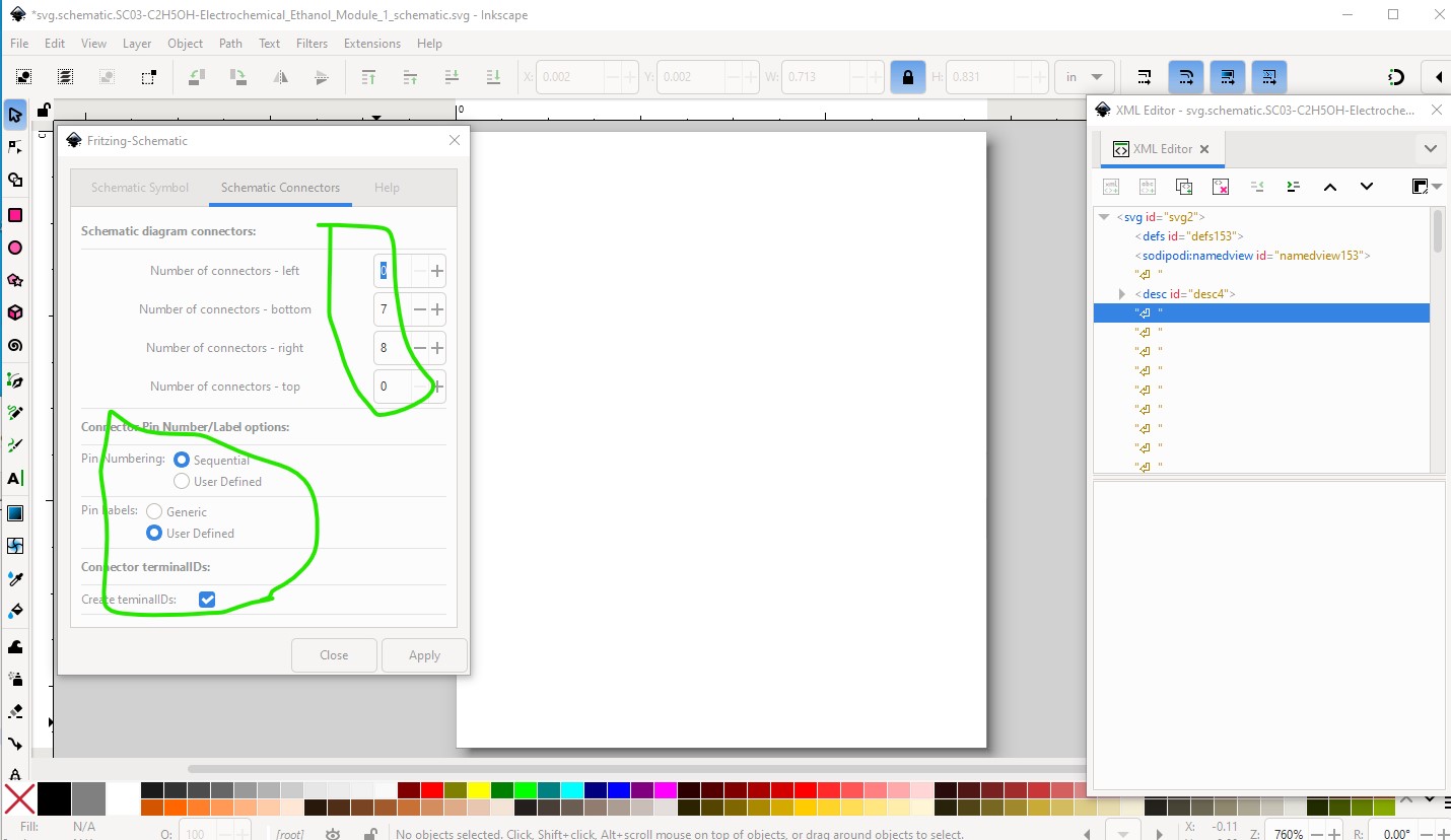
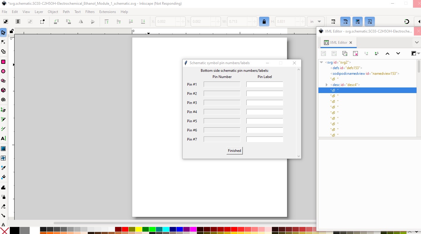
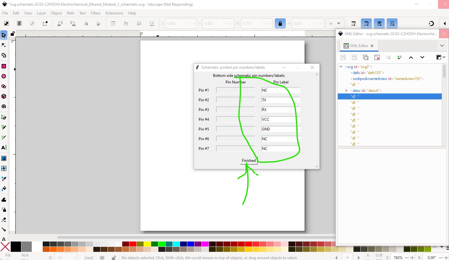
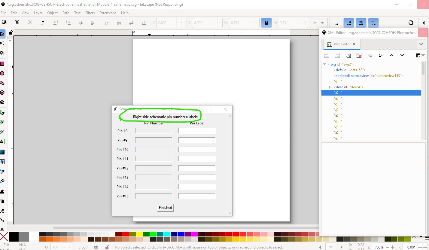
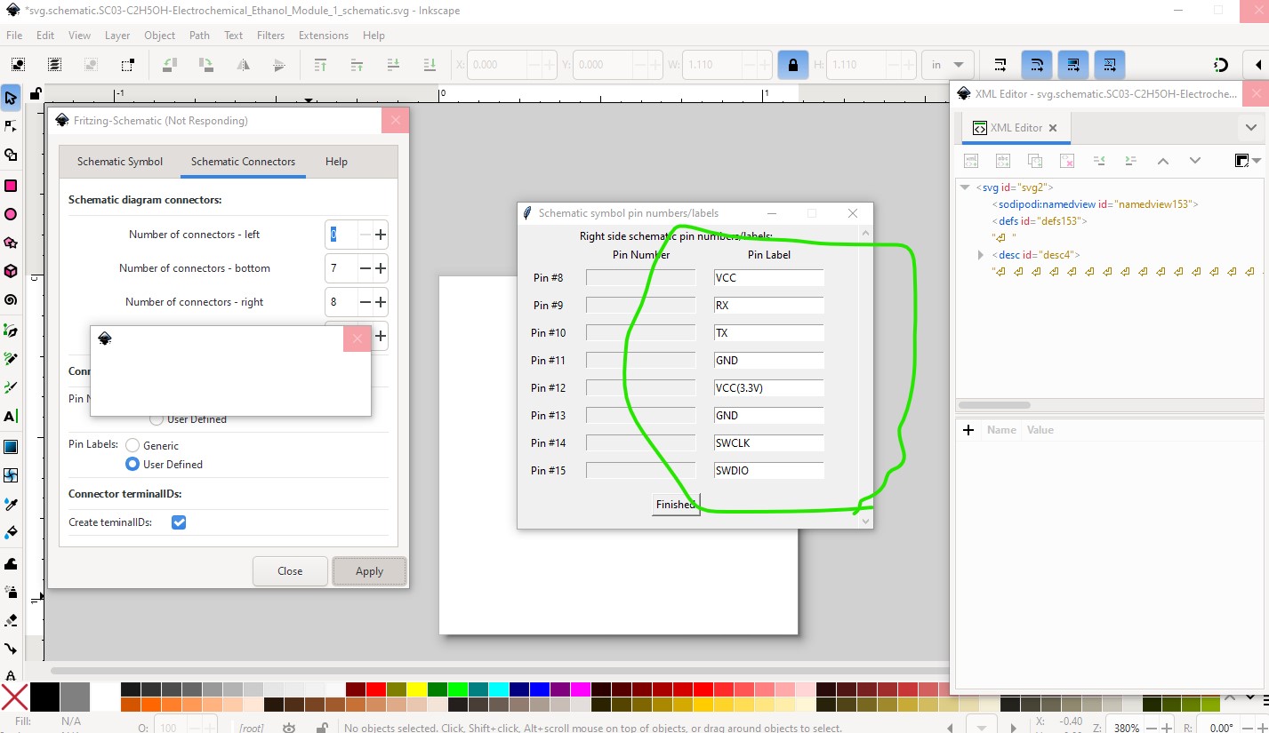
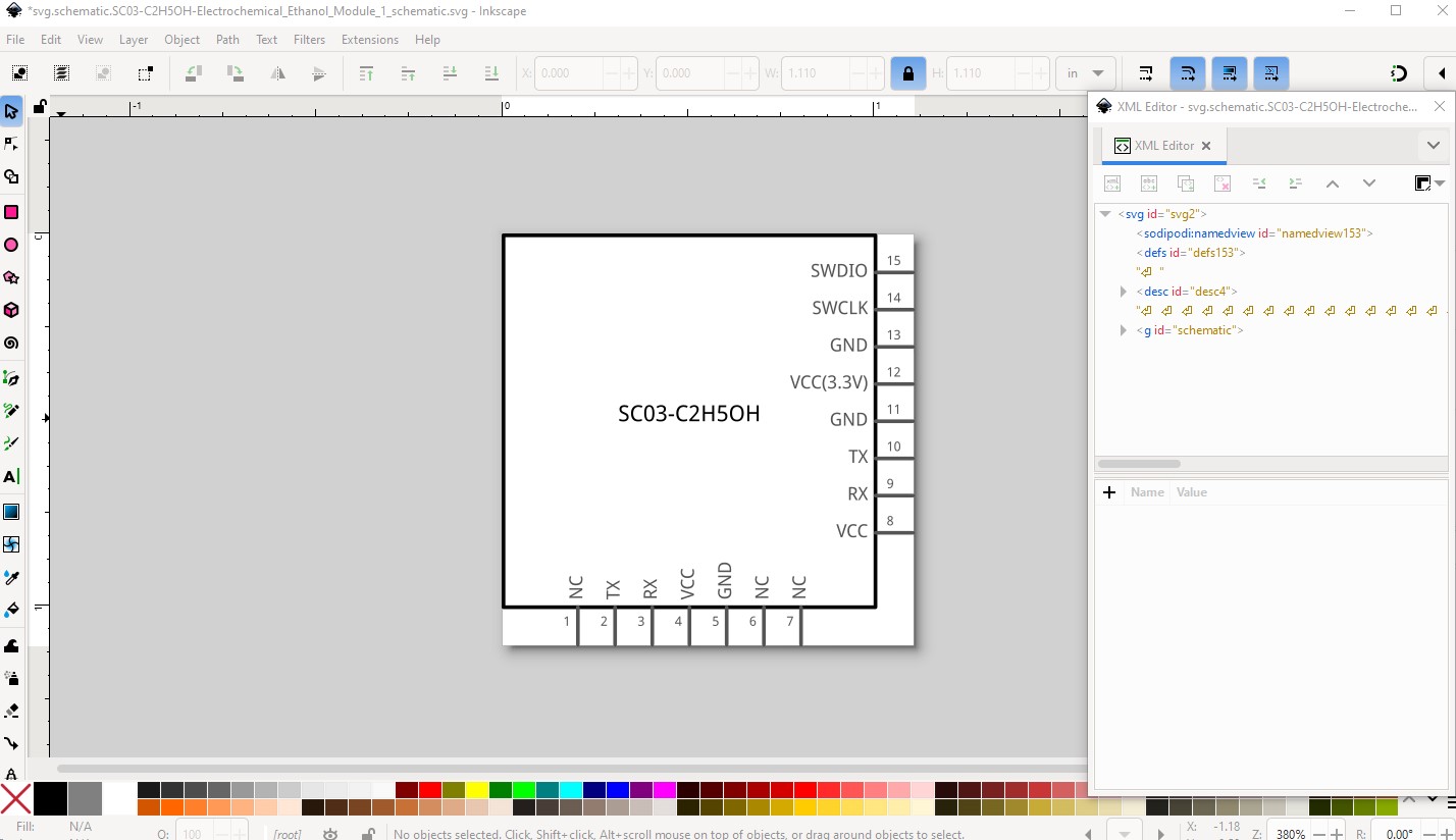
Here the pins are renumbered and in the correct order and we are finished with breadboard. So now move on to schematic. I chose to use Randy’s Inkscape extension to do schematic so I need to set it up. Here I set the label to “SC03-C2H5OH” and the size to 1in x 1in (as the that will accommodate all the necessary pins.) It may be worth downloading Inkscape just to use the schematic extension to make schemaitcs as it is much easier than doing it manually.
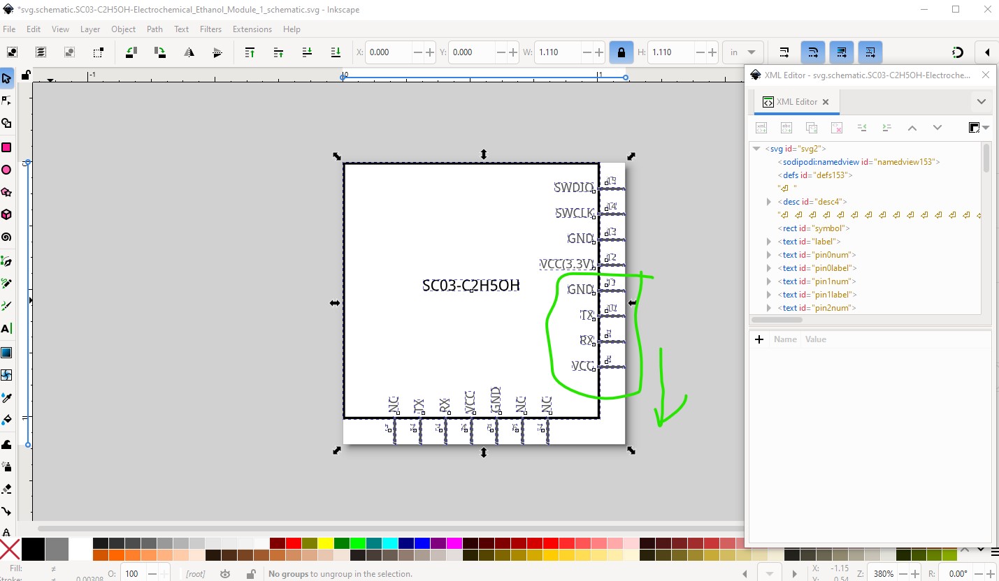
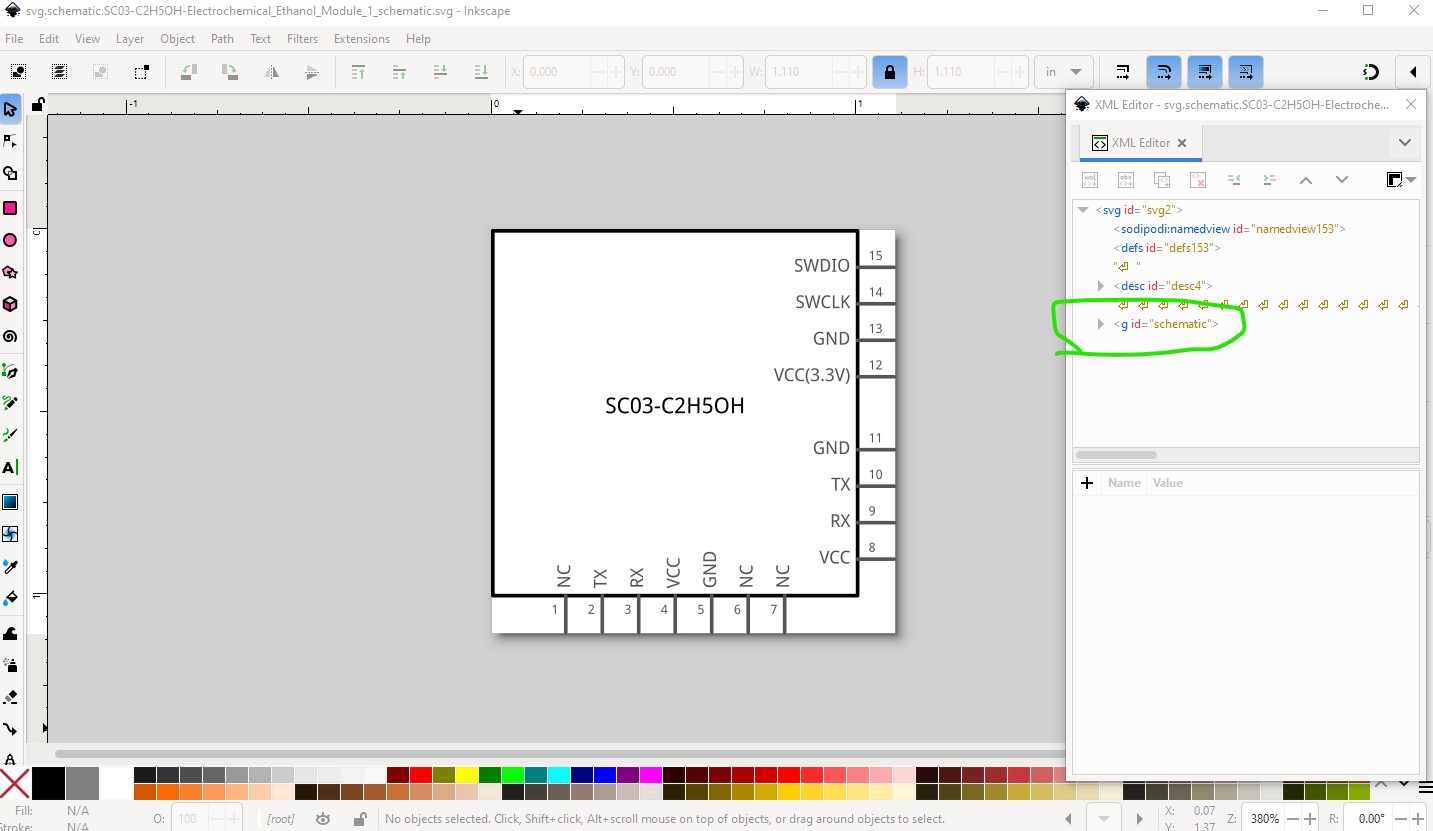
Now I can save the schematic svg and move on to pcb. To make pcb I copied the breadboard svg in to the pcb svg then edit it with Inkscape. First I ungroup the svg and delete all the parts not needed in pcb (the bottom connector which won’t connect to pcb and all the text.)
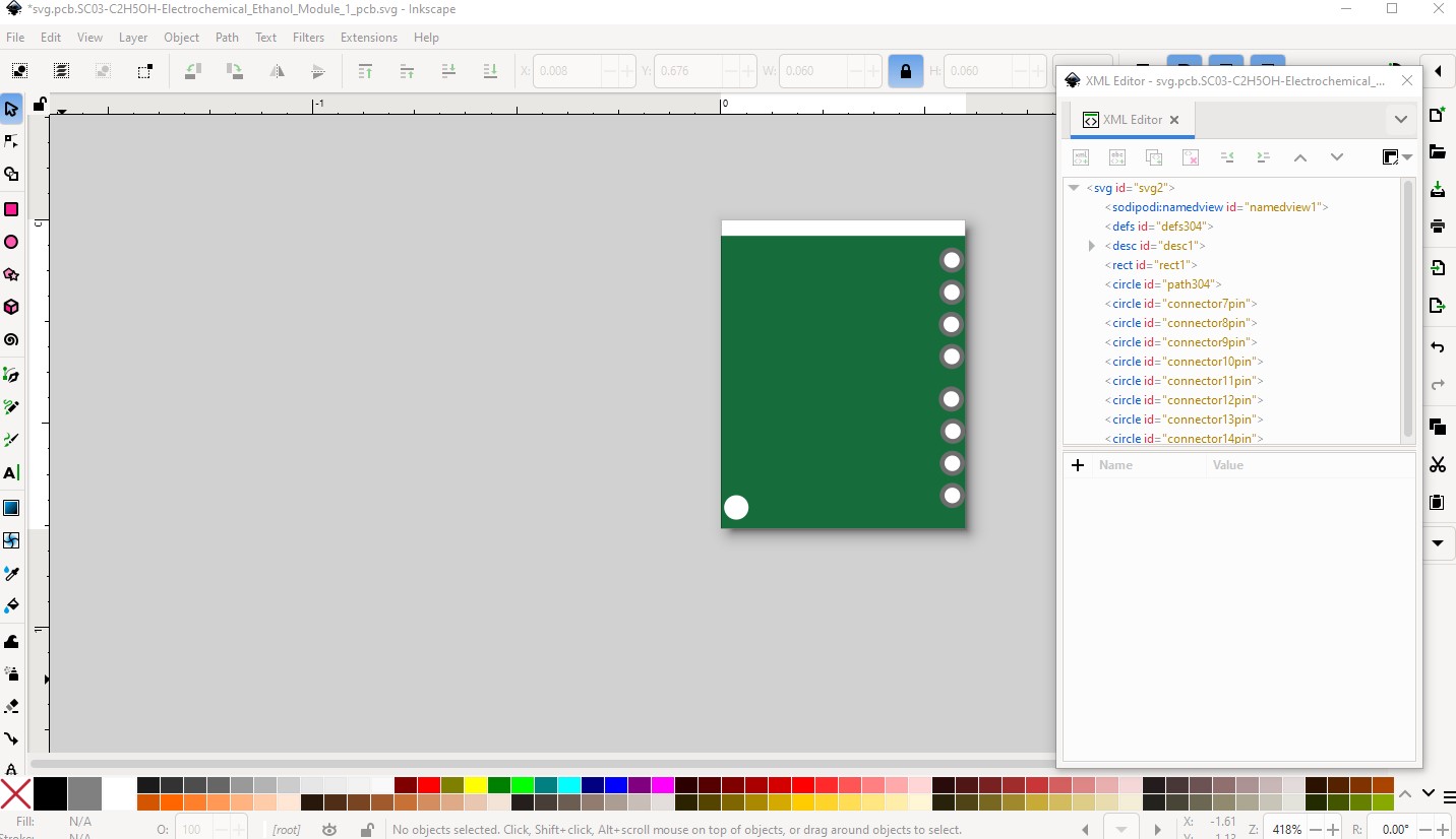
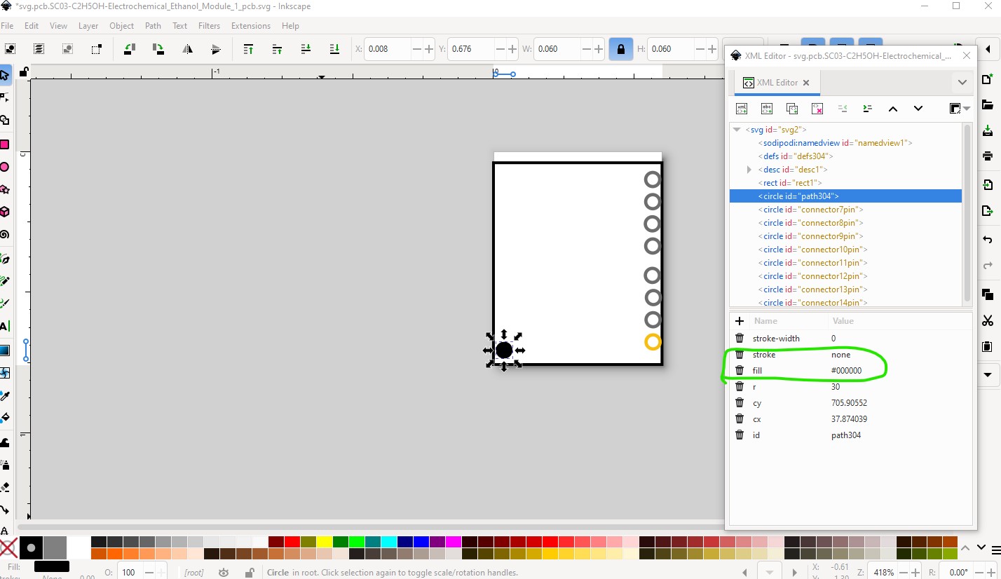
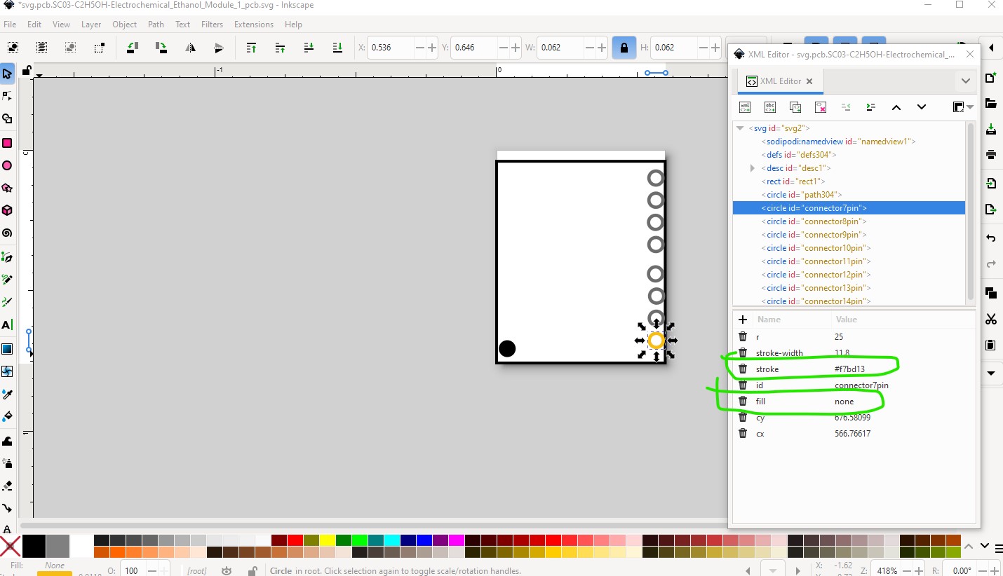
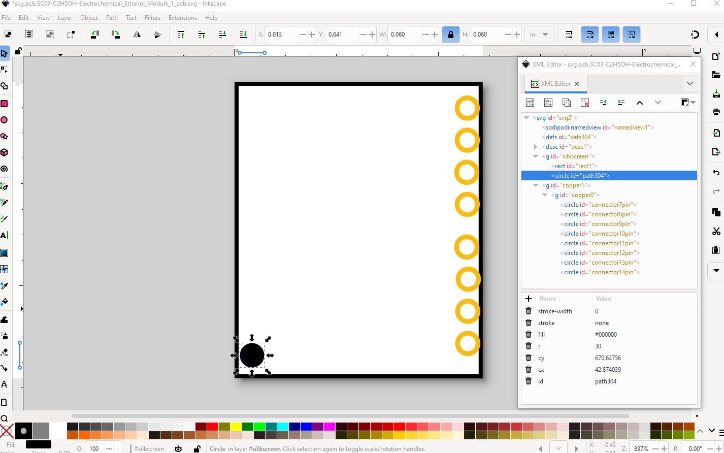
Then change the green rectangle in to fill none, stroke #000000 to make a rectangle the size of the board and change the connectors to the colors appropriate for pcb and the fill from #ffffff to none. The mounting hole (which will be in silkscreen) changes from #ffffff to #000000.
and we can save the pcb svg as completed. Note connectors0-7 (the bottom connector) are not in the pcb svg. As a result we need to manually edit the .fzp file to remove the pcb definitions for those pins. Parts editor at present (and possibly in the future) can not do this so you need to edit the fzp file manually (and of course know how to do it!) To start with the connector looks like this:
Once that is done for the first 7 pins we need to adjust the bus definitions (which can be done in parts editor although I find it easier to just edit the file!) The current bus definition looks like this:
Yes making parts is complex and tends to bite (or simply not work correctly) without warning. It takes a long time to understand all the interactions and get them right. That is why if you only need a part or two it is much easier to let one of us with experience make it for you.