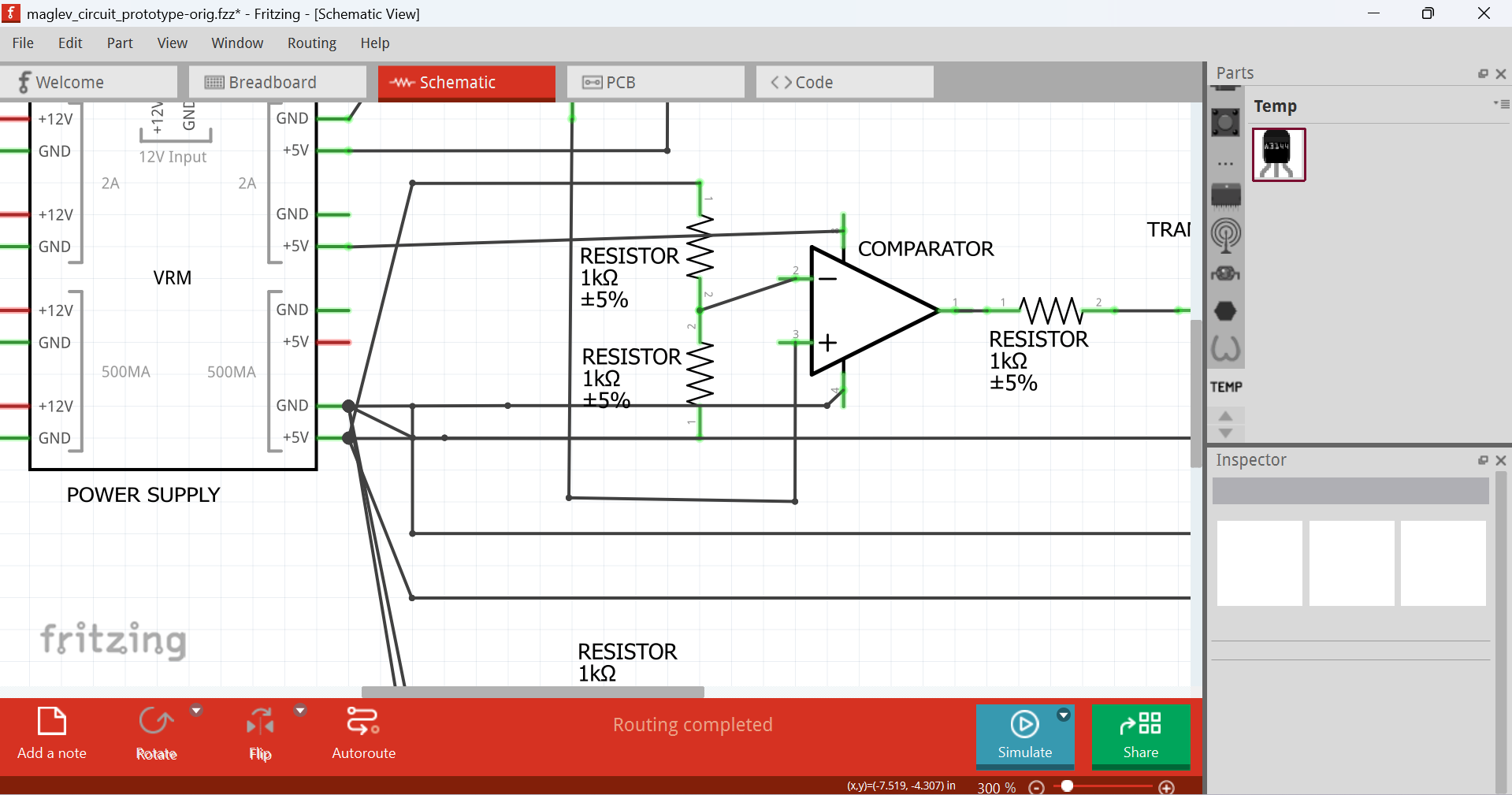
As you can see in the above image, the circuit looks fine.
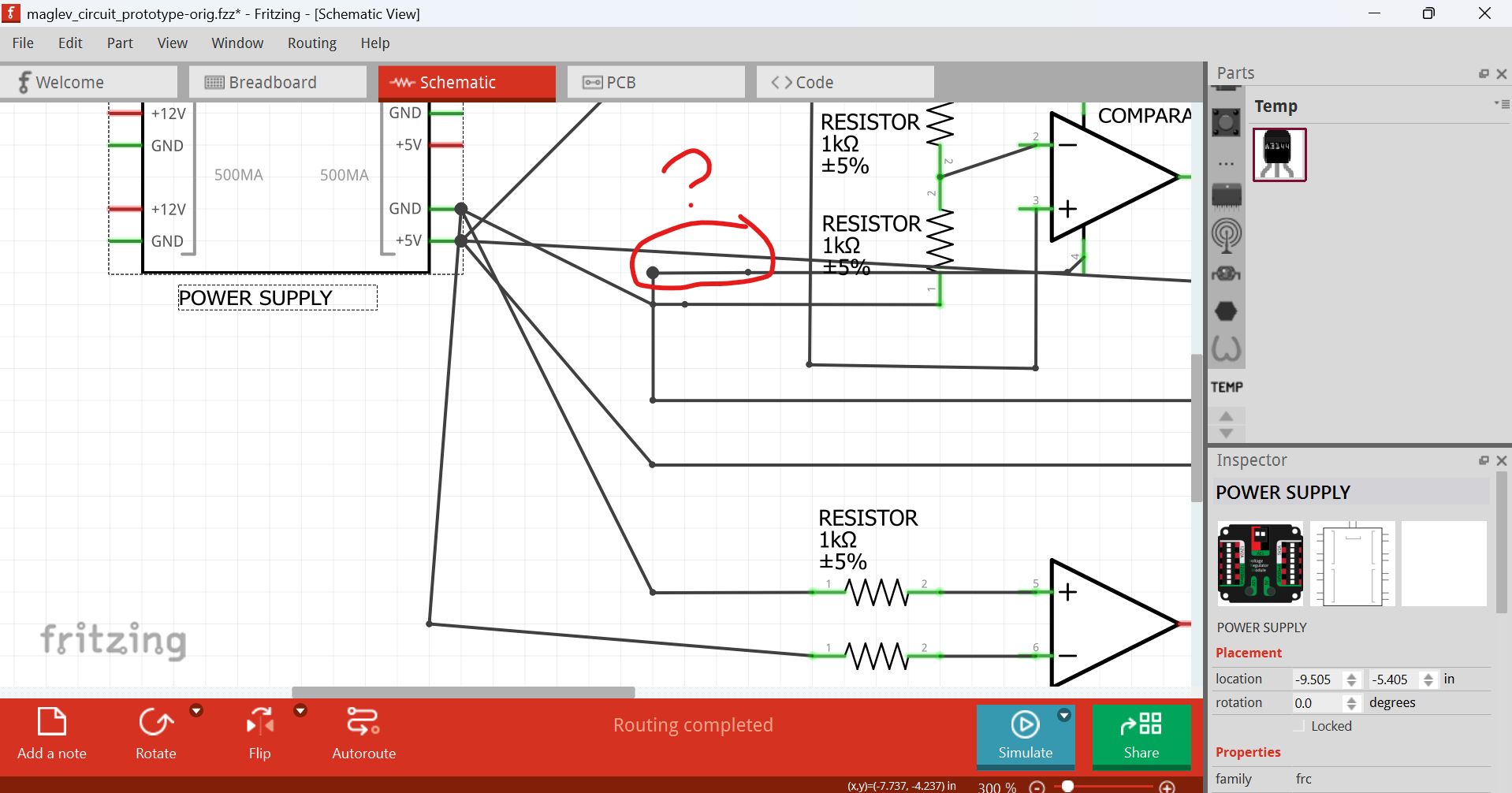
However, if you drag the VRM out, you’ll see this
But if you drag that loose end, uou’ll see
Is this a kind of bug??
maglev_circuit_prototype.fzz (18.9 KB)
Note:
The sketch came from:
So im absolutely new to fritzing and circuit designing and i do not know how to make a voltage divider for a lm358 , i cant understand how to make it . for context im making a circuit for a maglev train project where i have to detect the magnetic field strength and adjust an electromagnet . when the magnet rises too high, the voltages will change accordingly, can someone PLEASE help me i dont know anything;-;. Thank you in advance .
(P.S: sorry for my bad english its not my 1st language)
and I’m currently doing it from scratch
maglev_circuit_RAPTOR7762.fzz (16.8 KB)
@vanepp any thoughts on this?
opened 05:03PM - 06 Jun 25 UTC
## Current Behaviour

As you can see in the above image, the circuit looks fine.
However, if you drag the VRM out, you'll see this

But if you drag that loose end, uou'll see

Is this a kind of bug??
[maglev_circuit_prototype.fzz](https://forum.fritzing.org/uploads/short-url/zd4shkBA9mD9aZcJSyFfRPPu0Um.fzz) (18.9 KB)
**Build:**
Version 1.0.5 [Qt 6]
**Operating System:**
Windows 11
**Steps to reproduce:**
See ## Current Behaviour
## Notes
Related to #4221
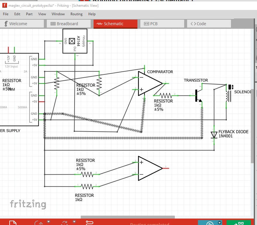
It doesn’t appear to be a bug or even wrong, just poorly laid out. Using ground symbols would help a lot. Here I moved the op amp a bit to untangle the connections then right clicked on the ground pin which shows correct connections everywhere.
although there is an error somewhere as this is wrong and it isn’t immediately clear why
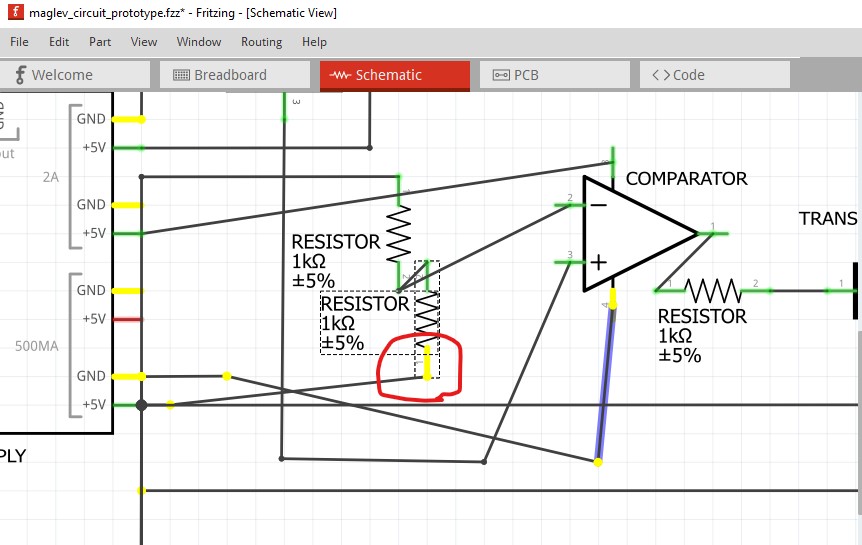
Ah! bad layout again. Ground is overlaid on the 5V wire (but not connected to it except visually)
routing schematic correctly should fix all issues I think.
Peter
Yeah so in the original thread I’m trying to redo the whole
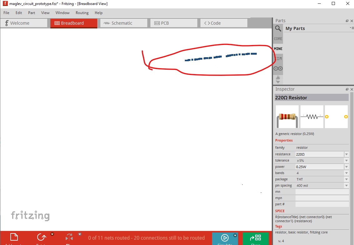
This is also suspicious
[image]
(as you can see the red cable)
maglev_circuit_RAPTOR7762.fzz (16.8 KB)
I’ll post this file and see if anyone can help
@Monke You dn’t have to reply in English. Though preferred, you can reply in any other language (your native language)
Can you help me to continue working on it?
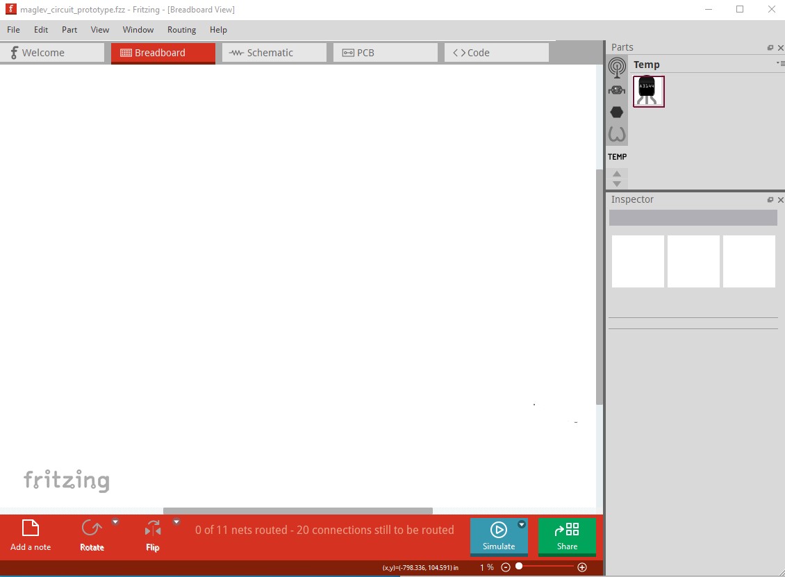
Sure, but the sketch appears to be corrupted. At least for me breadboard is appearing blank (and it shouldn’t be.) On load an image of a full size breadboard appears for an instant but when the load completes breadboard is blank (and with parts in the sketch it shouldn’t be!)
moving the scroll bars doesn’t find any parts. Yep it is really broken. Dragging a resistor from core parts in to the sketch doesn’t work.
releasing it which should write it to breadboard doesn’t do anything apparent (no resistor.) I expect the place to start is to create a totally new sketch from scratch and import the hall effect part from the original sketch and go from there.
Peter