While I’m not all that familiar with the NodeMCUs, there look to be a bunch of digital pins available in this pinout diagram:
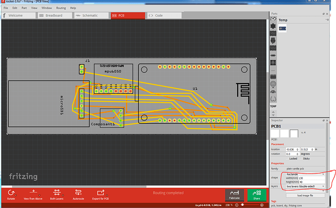
both s2 and s3 on the top of the board (unused on your sketch) show as being GPIO pins (and thus digital input/output presumably if configured that way.) In addition to the issues @microMerlin pointed out, you have a few more (some Fritzing, some not.) Assuming the sketch is intended to be in the rocket, the space shouldn’t be an issue. Here is your sketch with pcb set to 13cm by 4cm (you can set that by selecting the grey backgound and setting the size in Inspector (the lower right window.)
rocket-1.fzz (102.0 KB)
There are a few Fritzing part problems though. The node mcu part is badly broken. None of the holes are drilled because they are all ellipses. There is a corrected version (which I have not checked) at the bottom of this post. Since the person complained that the part had no holes, I expect you have the first one here ![]()
as well both the sd board and the bmp80 board have pins that are too small for a .1in connector (although wires should work fine.) The non Fritzing problem is that you don’t have a power source here. I assume that a battery will connect to the nodeMCU somewhere, but the connection isn’t shown in the sketch (and this won’t work without power!) Assuming you need access to the usb port on the nodeMCU for programming, the layout I used will block access to that, so would probably need to change. I expect weight will be an issue here as well, so you may want to find a smaller (and therefore lighter) SD card as well.
Peter
