Hi there,
When I’m using Fritzing, it is typically to aid in the layout of stripboard PCBs, using the BB view.
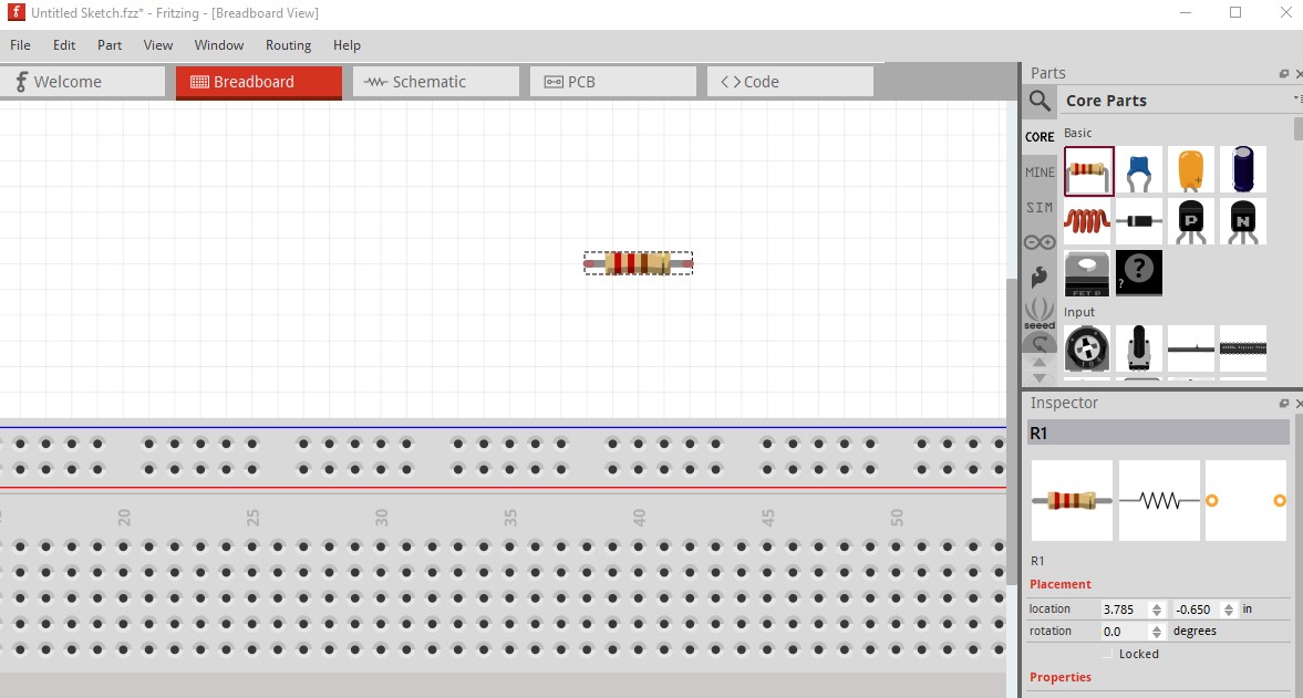
In real life, resistor spacings can vary widely and using a wire to extend a leg is not a tenable solutions because the resistor needs to be ‘anchored’ to a hole, meaning it is then conducting with that track.
Changing the basic resistor’s footprint does nothing in the BB view - can we please have a new part to solve this? We should be able to select everything from 2 adjacent holes (upright orientation) to spanning, say, 7 holes.
If there is something I can do to aid in the production of this, please let me know.
for the 0.1in resistor do a google search of the form “fritzing part Resistor Mini.fzpz” to find a variety of implementations. For perf board use you also want to search either google or the forum search bar for “top view” which is the typical label for parts designed to work on perf board (they have exactly the outline of the real part to fit on perf board.)
I have found the collection of top-down view components for the breadboard view. It was very kind of everyone to contribute these to the community, but the problem is that you either need to a) remove and replace your parts depending on size requirements once you’ve started your layout or b) you have to know your layout first, which defeats the whole purpose of using Fritzing as a ‘sandbox’ for easily working out a preferred PCB layout.
The working process for designing a PCB/stripboard is to create the schematic, then with the aid of the software’s rat’s nest lines, create a PCB layout.
This is why we need components where the size/orientation can be changed without needing to substitute a different .FZP part fie.
What support exists within Fritzing to change BB component form factors?
None. The size of parts is fixed at creation. To change the size you need to change the part. That said I am not sure what you are trying to do. The parts have a physical size which is fixed (orientation can be changed within Fritzing.)
Each individual part has fixed images / form factors in each view. However, you can substitute parts within the same family, and each part in the family can have a different form factor. Still need to have each individual part and form factor to be able to set that up.
The size of parts is fixed at creation. To change the size you need to change the part.
Hi Peter. In the spirit of constructive criticism, I think this is a mistake or at least a missed opportunity.
Here’s a short video that I feel conveys the problem quite well: https://youtu.be/RmnpW-alvhw
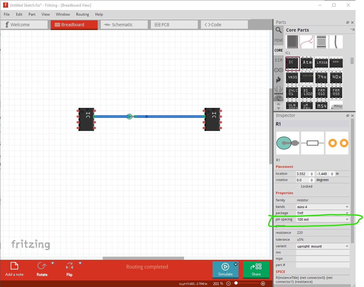
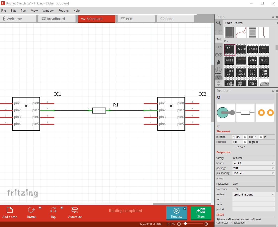
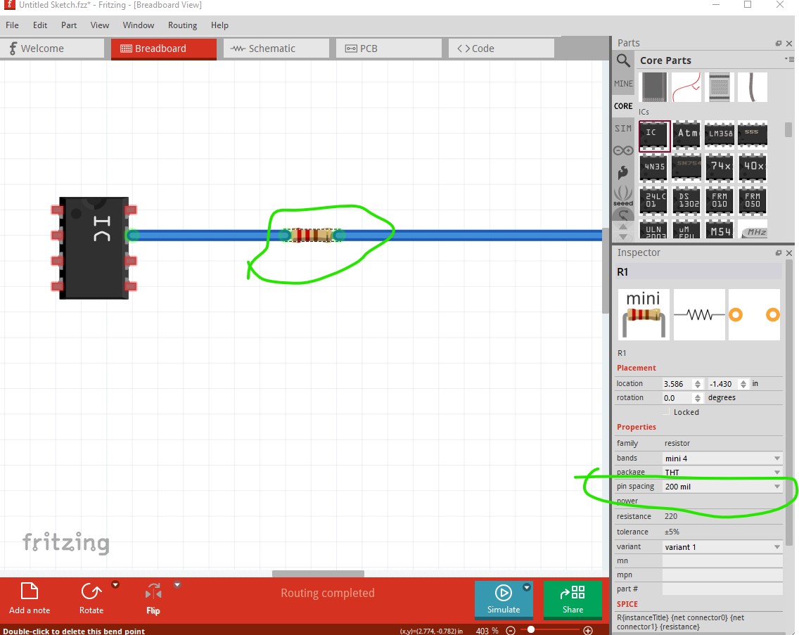
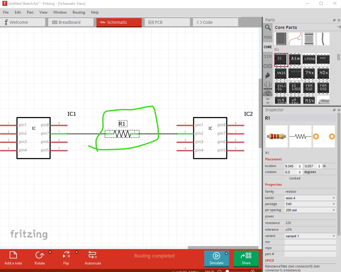
Sorry for the late reply, I needed to get an adapter to get the audio from your video, which took a while. With the correct parts what you want works now with no changes (and I expect changes that modify how parts are made will be considered too much work for too little gain, but I am not a developer!) Here is an example of what @microMerlin was referring too. I started with a 0.1in vertical resistor (this one has a few problems, I think there is a better one available with color codes included but I didn’t immediately find it!) Here the resistor is on 0.1in centers (i.e. 1 pad pair on perf board) and is connected between tqo ICs.
which changes schematic without me doing anything leaving the connections as is. If you actually need to sway the part, using delete minus instead of delete will delete the part but leave the wires connected. You then need to drag the wires to remake the connections (which is usually an extreme hassle.)
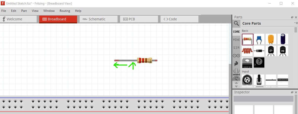
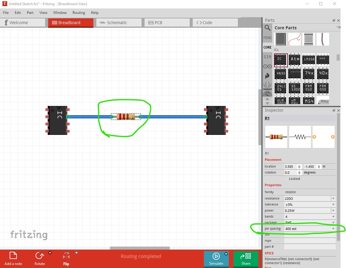
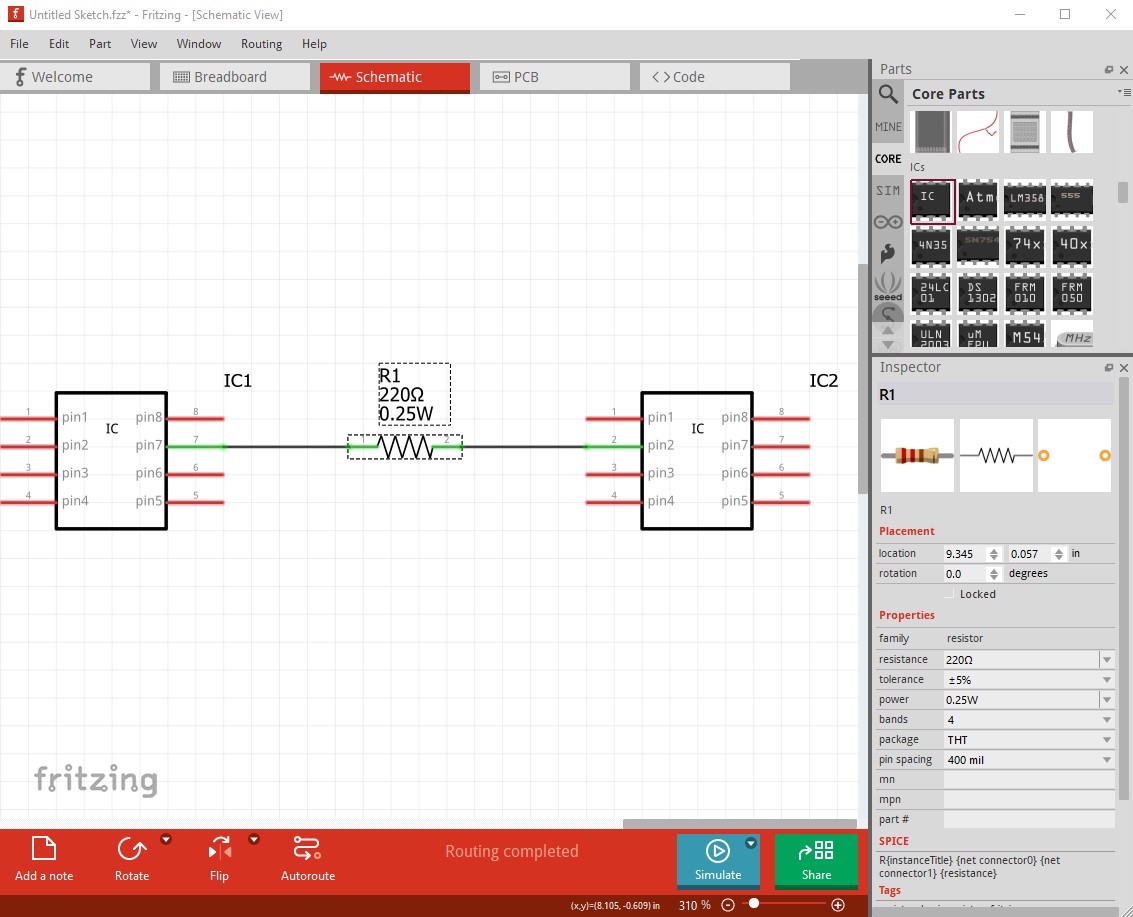
move up to 400mil and the same thing happens. Making new parts for 500, 600 whatever mils will work fine (but is a lot of work.) As noted earlier normal resistors are bendable lag parts so you can click in the connection point and extend it however long you need.
With sufficient experience making parts, the same can be done for other types of parts. As noted they need to all be in the same family to swap for each other and some of the parameters (such as resistor color codes) are part of specific families (and are in fact hard coded in the Fritzing app) but if you know enough about part creation you can often work around that too. So I would say that what you want to do can be done now with no major changes to the code (which I think are unlikely to happen!)
They are variable footprint. However, in the breadboard view, in the standard use case, the simplified and standardized view outweighs the exact physical representation.
When you have a different requirement, like, you want to have a 1:1 image of the resistors on a breadboard, or even solder SMDs to a stripboard, this needs a bit more fiddling, e.g choosing specialized parts.
There are multiple ways for improving Fritzing for the stripboard. One very common problem is that the breadboard view doesn’t support top and bottom views. (Which the PCB view does)
Maybe adding a bin with parts that are optimized for the stripboard would help more, than a deep change of the behavior of Fritzing most used electronics parts?
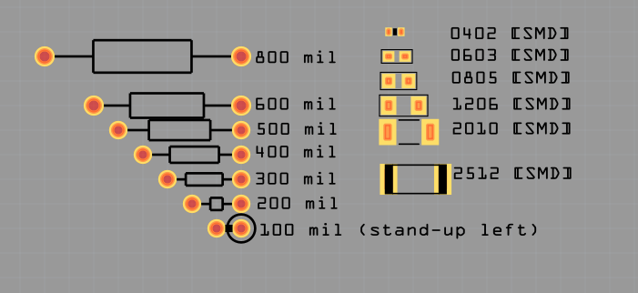
Unrelated observation: I’d read the symbol for the 100mil resistor as “stand-up right”. Is this only me?
There are stand-up right and stand-up left (the difference being in which pad the resistor body is centered in case you want to put the body in a specific place.
Yes, but the circle that symbolizes the resistor is on the right for the “stand up left” part. You could view it from the perspective off the resistors legs, than the right leg is sitting, and the left leg is standing. But my intuition is that most people would expect he circle on the left side for the stand up left resistor.
I do not think we need a big change in Fritzing´s behavior. I would just rename the “pin spacing” to “PCB pin spacing” and add another property called “BB spacing” to all parts and this property will change just the BB view. From my point of view, a PCB and a BB are different implementations of the same schematic and they may need different spacings for each implementation. I would avoid having SMD parts for now in the BB, but if necessary the BB pin spacing could have an option like “same as PCB”.
When using the “same” part for breadboard and PCB, they will have the same footprint. However a common (as I see it) case would be to use a THT version of a part for breadboard, and SMT for PCB. Or an SMT carrier in BB. So I too would like the ability to change the footprints independently in each view.
I do not see any need for up-left and up-right versions of resistors. A part flip or rotate should make them equivalent. So a single vertical, or stand-up part should work.