Over all a good part but a few problems. This tutorial on parts making may help if you haven’t seen it:
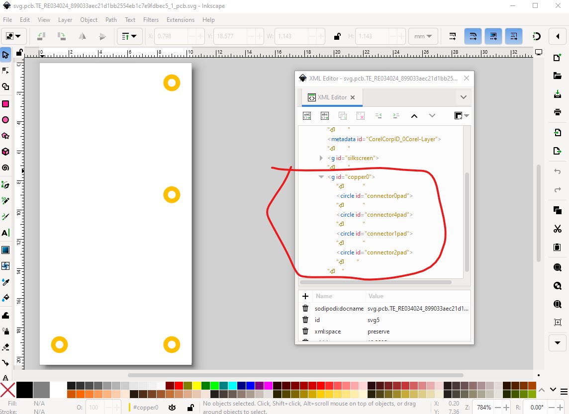
Starting in pcb, you are missing the copper1 group making this a single layer part (and thus no hole will be drilled for the pins!)
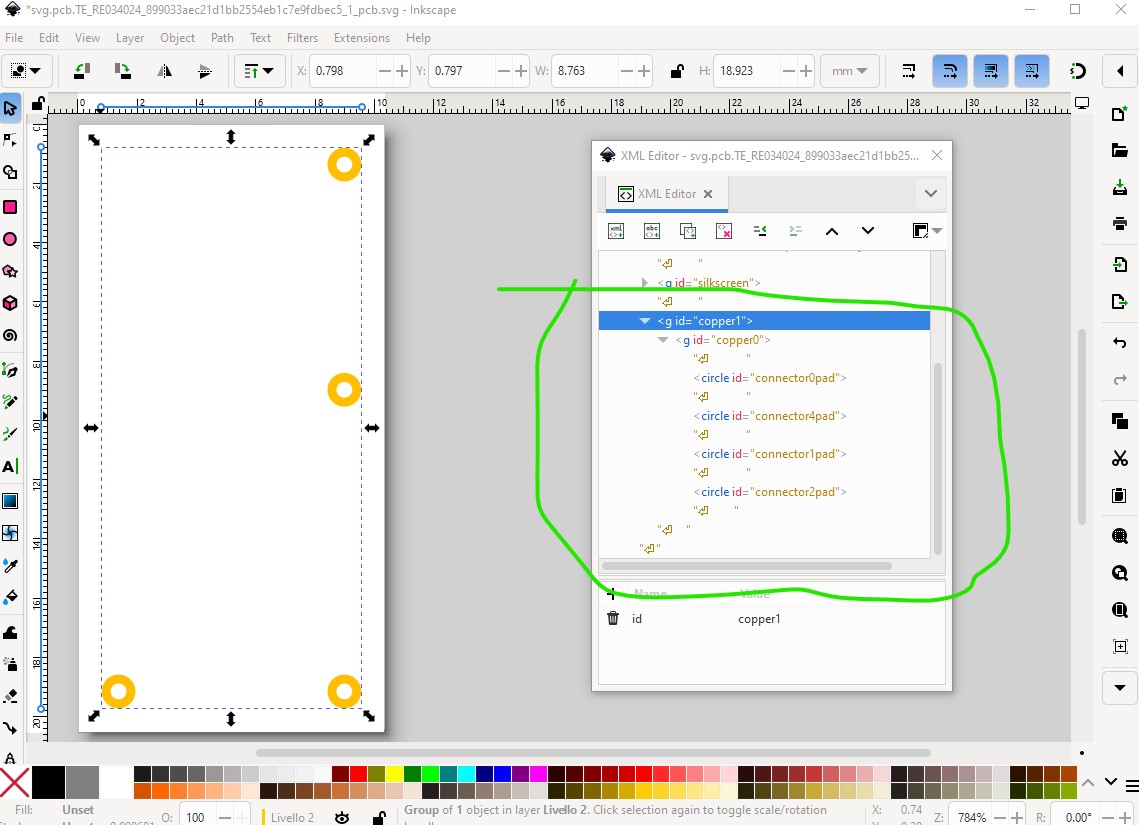
It needs to look like this to work
then the pin hole is too small (this is from the gerber output drill.txt file that specifies hole size)
original holes
; NON-PLATED HOLES START AT T1
; THROUGH (PLATED) HOLES START AT T100
M48
INCH
T100C0.038000
T101C0.021000
%
The 0.038in hole is the standard 0.1in header, the 0.021in hole is the current relay pin. From the relay data sheet the hole size should be 0.052in (1,3mm)
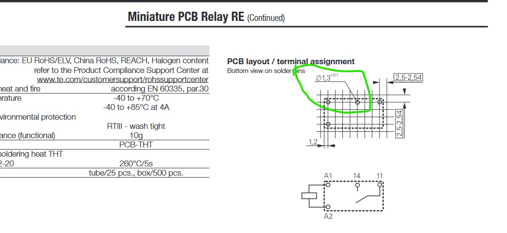
In Inkscape (which appears to be what you are using as an svg editor) the hole size is
hole_size = pad_diameter - (2 * stoke-width)
or in this case with a stroke-width of 20 (note that I rescaled the pcb svg to the standard Fritzing scale) that works out to
0.052 = 0.092 - (2 * 0.02)
so the pad diameter is 0.092in with a stroke width of 20. Which produces this gerber output
corrected holes
; NON-PLATED HOLES START AT T1
; THROUGH (PLATED) HOLES START AT T100
M48
INCH
T100C0.038000
T101C0.052000
%
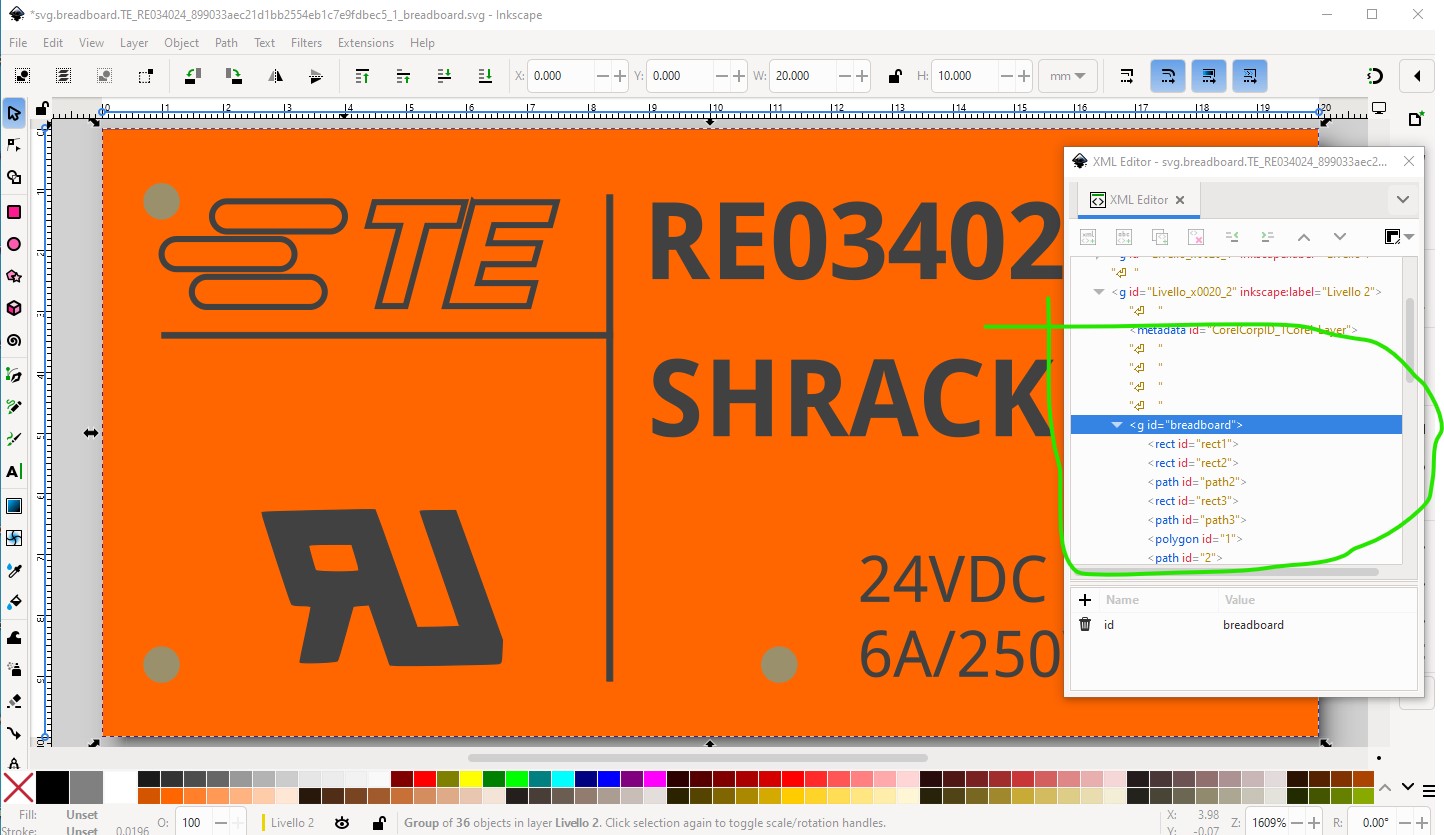
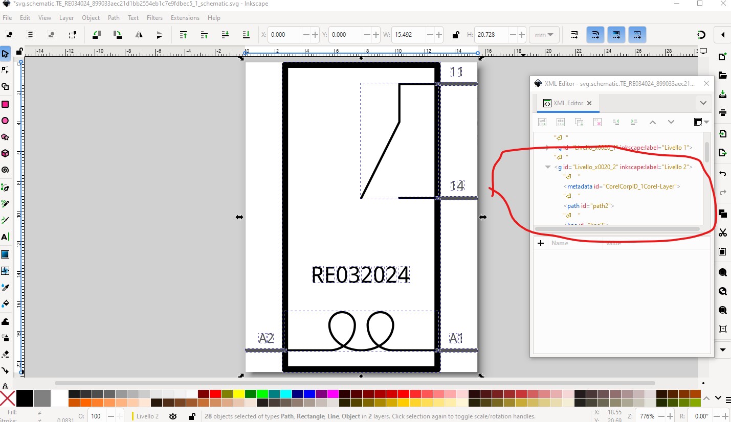
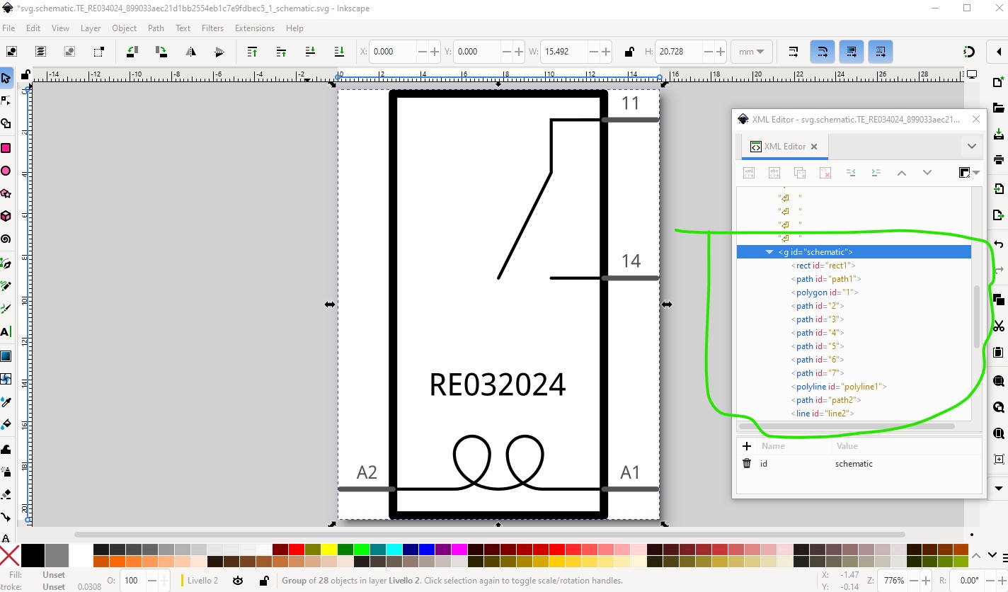
Then the layerIds are missing in both breadboard and schematic. This will cause the part to not export as an image in Fritzing.

to fix it group the entire svg and name the group breadboard.
the same for schematic except the layerId is schematic
to
Last it is desirable to have a label in the .fzp file like this
<label>RY</label>
Which will replace the part1 label with RY1 indicating a relay. All of these changes are included in this corrected part.
RELAY SPST form A-fixed.fzpz (21.8 KB)
because I didn’t change the moduleId you will need to delete the current part from your mine parts bin, then shutdown Fritzing answering yes to the save new part and save parts bin prompts then restarting Fritzing before it will let you load the new part.
Peter