The triangles have been produced and are in the hands of the shipping company.
Can’t wait to see what I created and if they work!!
The triangles have been produced and are in the hands of the shipping company.
Can’t wait to see what I created and if they work!!
OK, the triangles have arrived. Now I need to find someone to place the LED’s and capacitors.
Does any one know of a service?
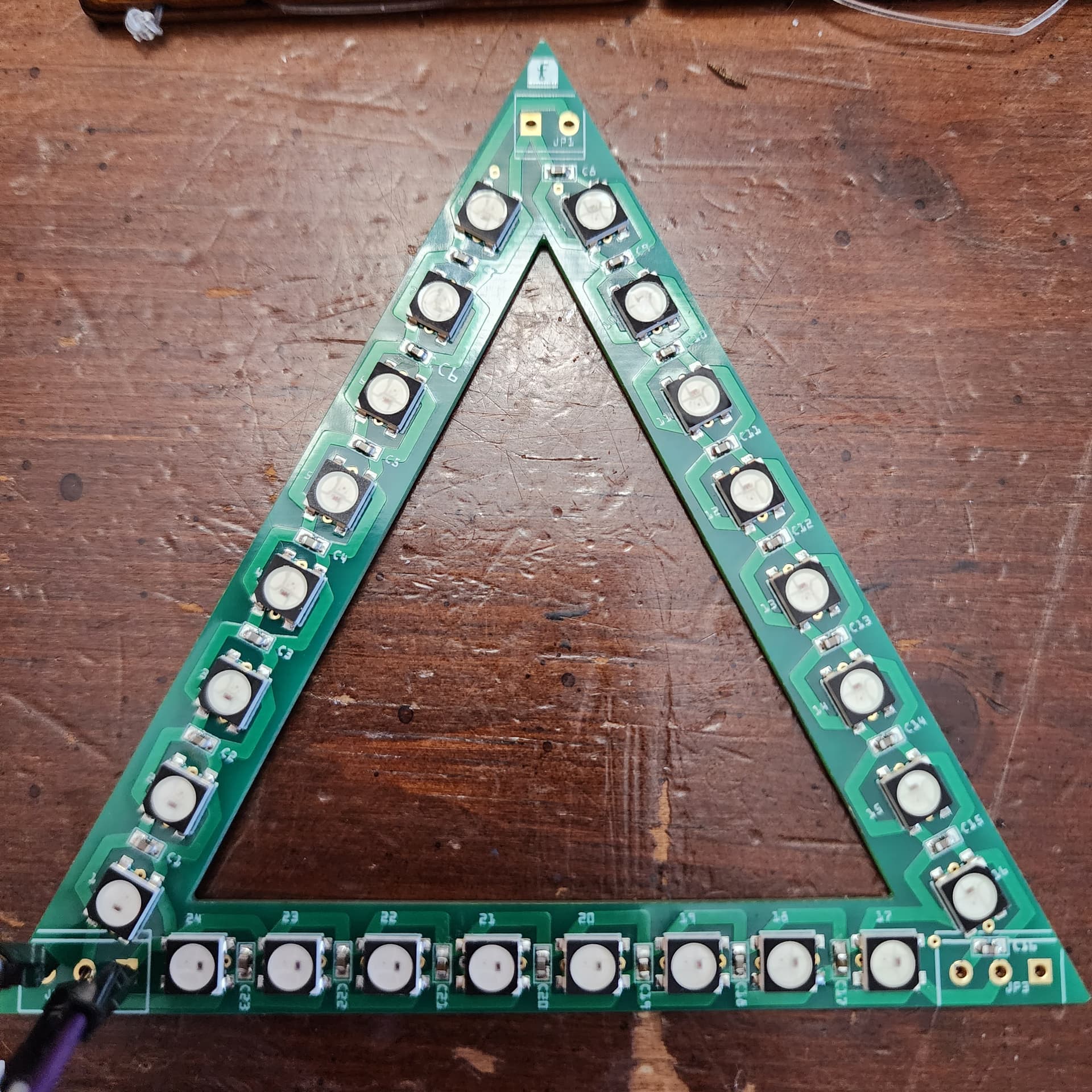
I kind of thought they would come with everything installed. Must have messed up on the order. Thought the parts were added, but I guess I didn’t do it properly, The do look very good tho, I’ll give them that.
Well, I went an order the boards completed with the parts. I used PCBWay as there seemed to be a lot of confusion with Aisler in regards to the Fritzing files that are generated. PCBWay did not have any problems and shipped me a completed product.
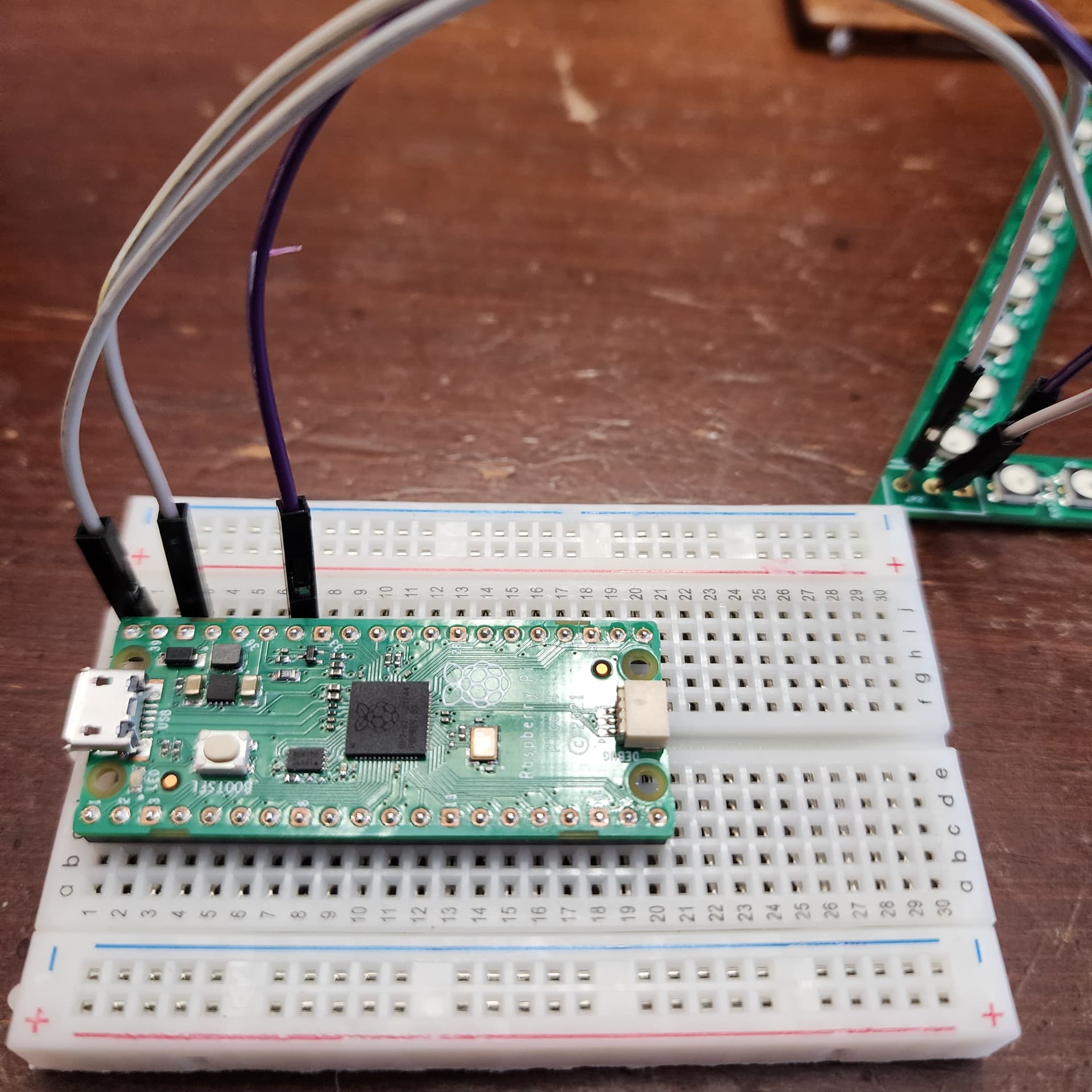
Now, I was hoping to run the script with the RPi Pico and MicroPython has it see to be the easiest to get around and the board is small. I have connected the Pico to the Neopixel Triangle and I can’t get any flicker of light on it. I will probably come down to power, but I would like to ask the community what they think. Point me in the right direction would be greatly appreciated.
My first guess would be the led driver code. On the Arduinos it is written in assembler due to the tight timing required by the led driver chips. You likely need to find the equivalent (assuming there is one which I expect there is!) for the Pico (or verify the pico is fast enough to not need it which is also possible.) I don’t expect micro python code will be able to meet the timing requirements (but I could well be wrong too!) If you have an Arduino, try and drive the board from that (I think the library you need for the led chips comes from Adafruit), if that works then that is probably the problem and you need to find an equivalent piece of code for the Pico. Also check that 5V is appearing on the chips with a voltmeter to make sure that power is being applied, but assuming you have power then timing is likely the next most likely issue.
edit: Looks like you need this driver if you don’t already have it:
https://docs.micropython.org/en/latest/library/neopixel.html
Peter
Thanks Peter.
When connected to the Pico via a USB cable to either a computer or with a 120 charging adapter I get 1.2 v all around the board, at the LEDs, capacitors and the holes. No LEDs light up.
I connected it to a Mini Switching Regulated Adjustable DC Power Supply and with 12.7 to 12.9 v and .27 amps the board lit up as per the script I had on the Pico. I pushed the voltage to 13, tried to measure the voltage on the board and it blew. All LEDS stopped. I was getting the proper voltage all the way around the board.
I think the LEDs are supposed to be 5V not 12V (although I’m not sure of that!) so 12V was likely a fatal mistake. USB is limited to about 0.5A and I think the LEDs can draw a lot more than that (I seem to remember about 100ma per LED but again check the data sheet!) so you probably want a couple of amp power supply. Note that because the LED drivers are asynchronous you need to provide enough power so that all LEDs being on at the same time won’t collapse the power supply (i.e. the power supply needs to provide number of LEDs * amps per LED of current because sometimes the LEDS will draw that much power and if the power supply collapses the LEDs will reset and may hang.
Peter
I’m going to connect one to an Arduino Uno and see if that will make any difference.
Would the number of Capacitors on the board make a difference in the current flowing at 5V? I’m not that electrical knowledgeable.
No. Only the number of LEDs that are on should affect the current. A quick look on Adafruit’s site doesn’t turn up a current per LED value, but I remember a number around 100ma per LED which would mean 2.4A at 5V with 24 LEDs (and the leds on adafruit are 5V not 12V!) so you would want around a 3A 5V power supply to power your board I expect. The low voltage on the 5V pins you saw can be caused by excessive current draw, as that is how it will typically show up (the power supply reduces the output voltage when it runs out of current capacity.) Its possible that applying 12V to the LEDs has blown them up as they are rated for 5.5V max.
Peter
Peter,
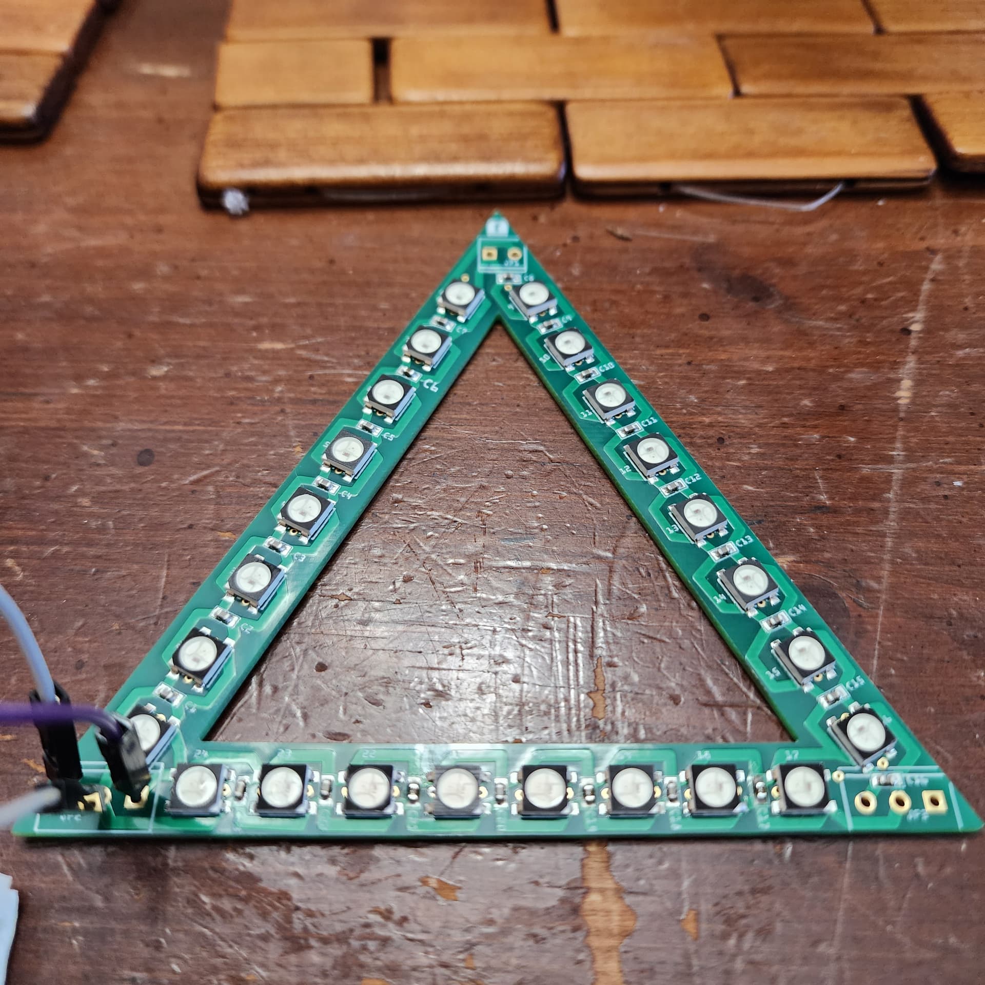
I’m just now crawling out from under the desk ![]() I feel sooo stupid. I had the wires connected wrong on the board. Reversed the power and the DIN and it works with the Pico, at least 24 LED’s do light up and used a couple of different scripts and all worked. The next iteration of the board, if there is one, is to place DIN, GND and VCC on the silkscreen portion of the board.
I feel sooo stupid. I had the wires connected wrong on the board. Reversed the power and the DIN and it works with the Pico, at least 24 LED’s do light up and used a couple of different scripts and all worked. The next iteration of the board, if there is one, is to place DIN, GND and VCC on the silkscreen portion of the board.
Alls well that ends well :-), congratulations!
Peter