Raspio Triangle Request

I’m looking to find or create a 24 LED triangle. A few years ago, Alex Eames from Raspio.tv launched a Kickstarter for a product he named, Raspio Inspiriing. I backed the Kickstarter and then purchased a couple of other items from him.

Now, I’m in the need of a couple of the triangles for a project I want to work on. On the Raspio.tv website they show as being sold out. I sent Alex an email inquiring about the chances of getting the bike kit or whether or not he would be bringing back into stock. This was a month ago and I’ve heard nothing. Then I looked at the website a little deeper and I see Alex has not added anything to his blogs for almost 3 years. I started to wonder if something may have happened to Alex.

If any one here knows Alex and can answer my questions, please let me know and thanks.

Any way, I start to Fritz around with the Neopixel straight 8 LED and attempted to link up the 3 strips.
LED_Trianglev2.fzz (22.3 KB)
It’s kind of crude at the moment.

How do I extend the corners? Perhaps there is a better option?

Your best bet would be to create a custom part for the triangle part. Although first you need to be able to get some if you need more of them.

Peter

1 Like

I have a pcb, made from Inkscape. Just two layers.
triangle_v1.05-plain

If you are willing (and able to, I think the LEDs are SMD and likely difficult to hand solder) to make boards, creating one shouldn’t be that hard (other than potentially the soldering) I don’t think. Given the triangle you should be able to drag in LEDs and make something close to the original.

Peter

PLAyed with it last night and have 24 LED’s on the board. They don’t fit great. Is there a freeform rotate for the parts.?

I’ll finish placing them, save and post it.

Yes. In breadboard select a corner and drag it to the desired position (the capture program won’t capture the little circular arrow that represents this, it should be obvious when the mouse is on the corner though!):

Default 5050 SMD led:

in pcb:

rotated 20 degrees (via Inspector)

Peter

1 Like

For accuracy and consistency, you can also just type an angle into the Inspector window. Or if the numbers are the same, copy and paste.

1 Like

Triangle_LED-v1.0.fzz (16.5 KB)
My first go at this.

For something with a consistent spacing like this, you can calculate the coordinates and angles. In a spreadsheet for example. Then type in both the position and angle for each part in inspector. For the bottom edge parts, you can simplify that some. Select them all, then on the “Part” menu, use “Align” and one of Top, Vertical Center, or Bottom.

Once positioned, autorouting should do a good job of the majority of the pcb traces. You might need manual cleanup at the corners.

The schematic view does not need to be done in the triangle shape. As far as the ‘logic’ is concerned, this is a simple chain of 24 addressable LEDs. 3 straight rows or columns of 8 would be accurate.

This is incomplete, so it is not clear what the second 4 pin jumper is for. I assume it allows chaining one triangle to the next. The 2 pin header is likely for power.

I see in the ratsnest wires in schematic that there connections from pin 4 labeled “N/C” to pin 3 “VCC”. I did not lookup the sparkfun part, but usually “N/C” is “no connect”. Similar, VDD is connecting to DIn. I would expect DOut of one connecting to DIn of the next, with the VSS, VCC, VDD on common buses. Check the information for the acutal parts you are using. Do they match the Fritzing Part?

1 Like

Looks pretty good. Here are a couple of improvements though. On the bottom set of LEDs use Inspector Y position to set them all to the same place in Y so they are straight:

Here I set y to be 2.679 for all the LEDs in the row (it varies around a bit in the last digit due to fp roundoff) which makes the bottom row straight. It would be a good bet to make the distance between each LED in X the same as well so they make a consistent pattern as well. Then I moved on the the left side, and dragged the ruler in from core parts and rotated it til it exactly matches the angle on the left side, then dragged it to line up with the bottom LED like this:

then using the x coord in inspector I moved the first couple of LEDs to match pretty much exactly the edge of the ruler by adjusting the x coord in inspector by small amounts til it matches the edge of the ruler. This makes the line up the angle exact.

This is the LED moved to its final position. Again making the distance between each LED identical will also help establish the correct pattern.

clicking on the ruler to select it will cause a white dotted line on the edge of the ruler making the placement of the LEDs easier to see.

Here is the sketch with these mods (and the ruler!) in place.

Triangle_LED-v1.0-improved.fzz (16.4 KB)

Peter

1 Like

A ‘trick’ for getting the correct spacing for something like this: Manually place the first and last (visually). Then get the coordinates from Inspector. Take the difference in the x values, and the difference in y values. Divide each of those by the number of parts in the ‘set’ to get the offset needed to make them line up perfectly. Again, a spreadsheet can fill in all of the coordinates easily. Doing that will reduce the round off error that could accumulate if adding the offset value to the previous part coordinates each time.

1 Like
LED Angle X Location Y Location
1 28.3 49.793 62.567 3.354 Difference X 1 to 8
2 28.3 52.521 55.524 53.147
3 28.3 57.176 48.401 56.501
4 28.3 60.872 41.301 59.855
5 28.3 64.560 34.206 63.209
6 28.3 69.065 24.903 66.563
7 28.3 77.889 17.633 69.917
8 28.3 76.627 10.560 73.271
9 151.7 84.454 10.517 6.485 Difference in Y 9 to 16
10 151.7 90.238 18.569 17.002
11 151.7 94.022 25.705 23.487
12 151.7 97.588 32.451 29.972
13 151.7 101.468 39.775 36.457
14 151.7 105.367 57.208 42.942
15 151.7 109.183 54.502 49.427
16 151.7 113.430 61.359 55.912

Here is a spreadsheet I made. When I get the 2 outer most LED’s set and subtract the difference and then divide by 8, the number does not match up with the higher placed LED.

When I attempt to change the value of “X” or “Y”, the values I place in the Inspector do not stick. They revert back to the previous value. Is this fixable?

Also, should the first LED start with Zero instead of One?

When there are 8 items, there are only 7 spaces. So divide by 7. Next, that is symetrical. I would expect the Y locations for the second set to be identical (reverse order) to the first set. Here is a snapshot of a spreadsheet I created from your numbers, then adjusted. I can not directly attach the spreadsheet because of forum rules. I zipped it into a .fzz file so that it would be allowed. Unzip that (rename to end in .zip if needed first), then open to see the formulas I used.

triangle-positions.fzz (6.5 KB)

The 2nd set of numbers for 9-16 used 10.56 for the starting Y, matching the Y value for 8, Since that should be directly across. Those numbers also ignore your ‘end’ position for 16. Instead, they are based on the spacing calculated for 1-8. Assuming that the triangle is symmetrical, the left and right should be at the same (relative) angle to the base. Your angle values confirm that.

The H-I columns are based on the angle plus calculated distance between 1 and 8, with (again) 9-16 being symmetrical. So that set of numbers is based on (only) the 28.3 degree angle, the x,y position of LED 1, the calculated distance to LED 8, and the X position for LED 9. Everything else is determined from that. So those 5 values can be tweaked to fine tune the positioning of all 16 LEDs.

I think we are seeing a Fritzing oddity (which I consider a bug!) The resolution of the x and y displays are too high. The 2 least significant digits are actually not, only the first after the decimal point is actually semi achievable. As an example here I set the values increasing by 0.01mm, then set them and recorded what the set position value was and what the increment is.

set entered
value value

10.641 10.59-10.7
10.520 10.46-10.58
10.400 10.34-10.45
10.279 10,23-10.33
10.159 10.10-10.22

What makes sense to me is assume we can’t position anything closer than 0.1mm (and then only roughly!) Because entering anything between 10.10mm and 10.22mm will result in a position of 10.159mm. I expect we need to take that in to account when doing the increment calculations. I think that an accuracy around 0.1mm should allow us to do what we want to do, but with some hassle doing the calculating. I would like to see the code changed to make this better, but there wasn’t a lot of interest in doing anything about it when it was brought up on github.

Peter

1 Like

@microMerlin

This is incomplete, so it is not clear what the second 4 pin jumper is for. I assume it allows chaining one triangle to the next. The 2 pin header is likely for power.

I see in the ratsnest wires in schematic that there connections from pin 4 labeled “N/C” to pin 3 “VCC”. I did not lookup the sparkfun part, but usually “N/C” is “no connect”. Similar, VDD is connecting to DIn. I would expect DOut of one connecting to DIn of the next, with the VSS, VCC, VDD on common buses. Check the information for the acutal parts you are using. Do they match the Fritzing Part?

Perhaps the choice of LED and the 4 & 2 pin headers are wrong. I’m basically looking at making something very similar to the Adafruit 24 led neopixel circle, but only in a triangle. The triangle could be run with an Arduino micro or something similar. This way, there are 2 5+, 2 GND and an In and an Out. Connecting together would not be that difficult.

I have the WS2812, but perhaps the WS2812b is a better choice? This would get a way from the VDD, VCC, VSS, etc.

Thanks for the spreadsheet. I see what you are saying regards to the location for x and y should be the same on either side. That’s what I had thought as well. But like I had post a bit above this post, when I change the numbers, they don’t stick. I can click on the up/down arrow on the coordinate and it will change and stick. But when I manually change it to say, 10.56, it somehow goes to 10.517.

The Adafruit part uses only 3 external input connection wires. Power, ground, and data (a fourth for output, when chaining). The description also talks about a “integrated drivers” and “very timing-specific protocol”, so if you are trying to match that, you will need to use the correct neopixels. That seems to be (originally) WS2812, then WS2812B, SK6812, and SK6812W from the datasheet page. All of which are 4 pin devices.

The ‘changing’ coordinates are (I expect) from limited floating point resolution, float point rounding, plus conversion of units to scale parts to match the sketch. ‘fixing’ is not likely to be simple.

Although perhaps not simple, I think it needs to be done. This is currently just plain wrong. It accepts values, then changes them in non standard (and non linear to the selected units!) ways. Preferable would be a more limited resolution output that is at least consistent (and preferably on dimension boundaries such as .1mm .2mm etc, I’d like to see a resolution around 0.1mm to allow for 0.5mm pitch SMD parts, although that may be harder!) Currently this is close to useless for positioning parts in pcb in my view. It looks to be converting to some internal representation (perhaps px for some unknown px value) then back to in or mm (but poorly!) It may be as simple as increasing the px value in use (i.e. if it is currently 72DPI change to 1000DPI assuming that doesn’t make a width limitation that isn’t acceptable!) Then round off the final number to create sensible values.

Peter

1 Like

I’ve started a new file using the WS2812b, the 4 pin led. I searched for the SK6812 in the parts list, but found nothing. I guess the WS2812b will work for building of the pcb. I see on the Adafruit website they talk about the WS2812’s as being used in older projects, while the SK6812’s as being used in newer projects.

Not all parts are in mm. Some parts will in “in”. That adds to the complexity. ‘rounding’ (after conversion) that is appropriate for one unit will not be good for the other. I suspect that the changes needed will not be in a nice contained section of the code. IF the interface to the internal storage, and back to display values was contained in interface code, it would be fairly easy. But if that had been done, there probably would not be a problem now. I expect that multiple sections of the code base are directly accessing the internal storage values, so the changes needed will be all over the place. Which in turns makes it very hard to verify that all of the needed pieces have been updated.

Sure, it would be good to have, but the resources needed to do it is likely to push it way down the priority list.

The ?better? solution would be keep the requested values (to some unit specific resolution limit) with the part, then convert that (as needed) to the common internal representation. The (suspected) conversion through units and scaling, rounding, truncation, then conversion back through the scaling and units creates a lot of potential for accumulation of floating point round off errors. This will also mix with DRC and the keepout distance. At some point, everything has to be constrained to that resolution for the checks to work. «actually the position of any copper needs to be constrained, which is not quite the same as the part position itself being constrained»

1 Like

With sufficient resolution (probably in mm as that is the one with higher resolution) that shouldn’t be an issue. If it works at mm correctly, there should be sufficient resolution for it to work in inches correctly as well. The current problem appears to be that the intermediate form of the coordinates doesn’t have enough resolution. The correct information must be present somewhere because gerber export works, parts with 0.5mm pitch can be successfully placed as can 8mil traces that connect them. That implies that somewhere in the database there are coordinates with adequate resolution to place them correctly with high resolution in gerber output (and presumably in the .fz file output as well!) What I believe is needed is to switch to those same coordinates for X/Y placement in Inspector. I agree that it may be a lot of work, but I think it is worth doing because as noted, the current method is pretty much unusable to successfully place components in pcb view. I expect comparing the coordinates in a .fz file with the coordinates obtained from Inspector should be illuminating (I expect (without proof currently!) that the ones in the .fz file are going to be a lot more precise than those from Inspector. I think (again currently without proof) that changing the positioning code in Inspector to use the same values that generate the gerber output should be fairly contained to the code in Inspector and should produce the desired output of having the setting entered in Inspector translate to the correct coordinates in pcb (which currently isn’t true!) and would be well worth doing or at least looking at to see if it is as easy as I think or there is a bigger issue. It seems to me we should be able to change to a more suitable set of coordinates (which must already exist somewhere for geber output to be correct) in the limited case of modifying the position values in Inspector. I agree that making a basic change that affects all areas is probably a non starter, but I think it is worth looking at if the specific code that displays and changes the x/y position of parts in pcb can be changed to improve the situation relatively easily. As noted a couple of posts back, currently a fairly wide selection of different fractional mm values map to a single output coordinate like this (in mm):

10.641 10.59-10.7
10.520 10.46-10.58

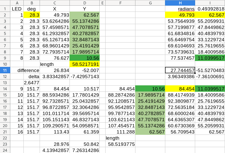
here anything in the range 10.59-10.7mm entered in Inspector X or Y coordinate field maps to an output of 10.641mm The next step is to 10.520mm (not an even multiple of the dimension setting!) The desirable outcome would be to be able to produce 10.50mm and 10.51mm (10.500 mm 10.501mm would be even better but perhaps not possible although I think that must be possible in gerber output indicating the data is there somewhere!) allowing the precise positioning of a part with 0.5mm pitch pins (at 1/10 the pitch value. I think that gerber output can do this, so that level of position data must be available somewhere and I think just not in use in this particular interface. It seems to me we maybe should be able to change this specific interface to use better data to get the desired outcome without making too large a change.

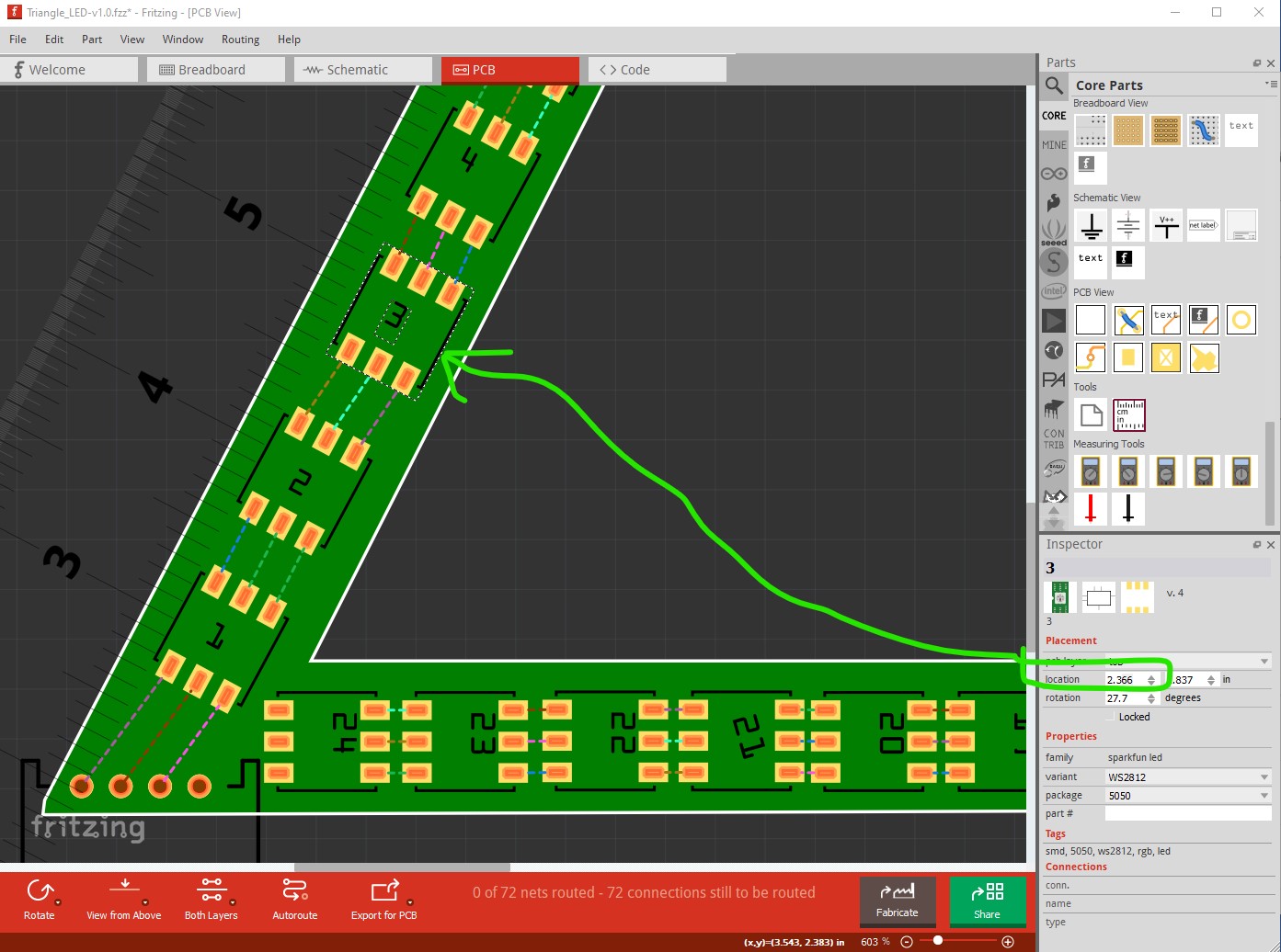
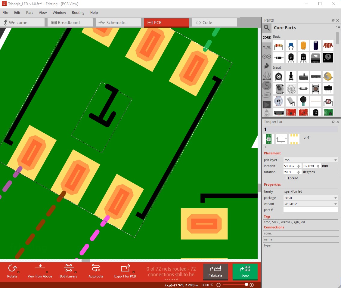
edit: I think I know what is going on here. The coordinates appear to be in pcb screen image space and are affected by the zoom factor like this:

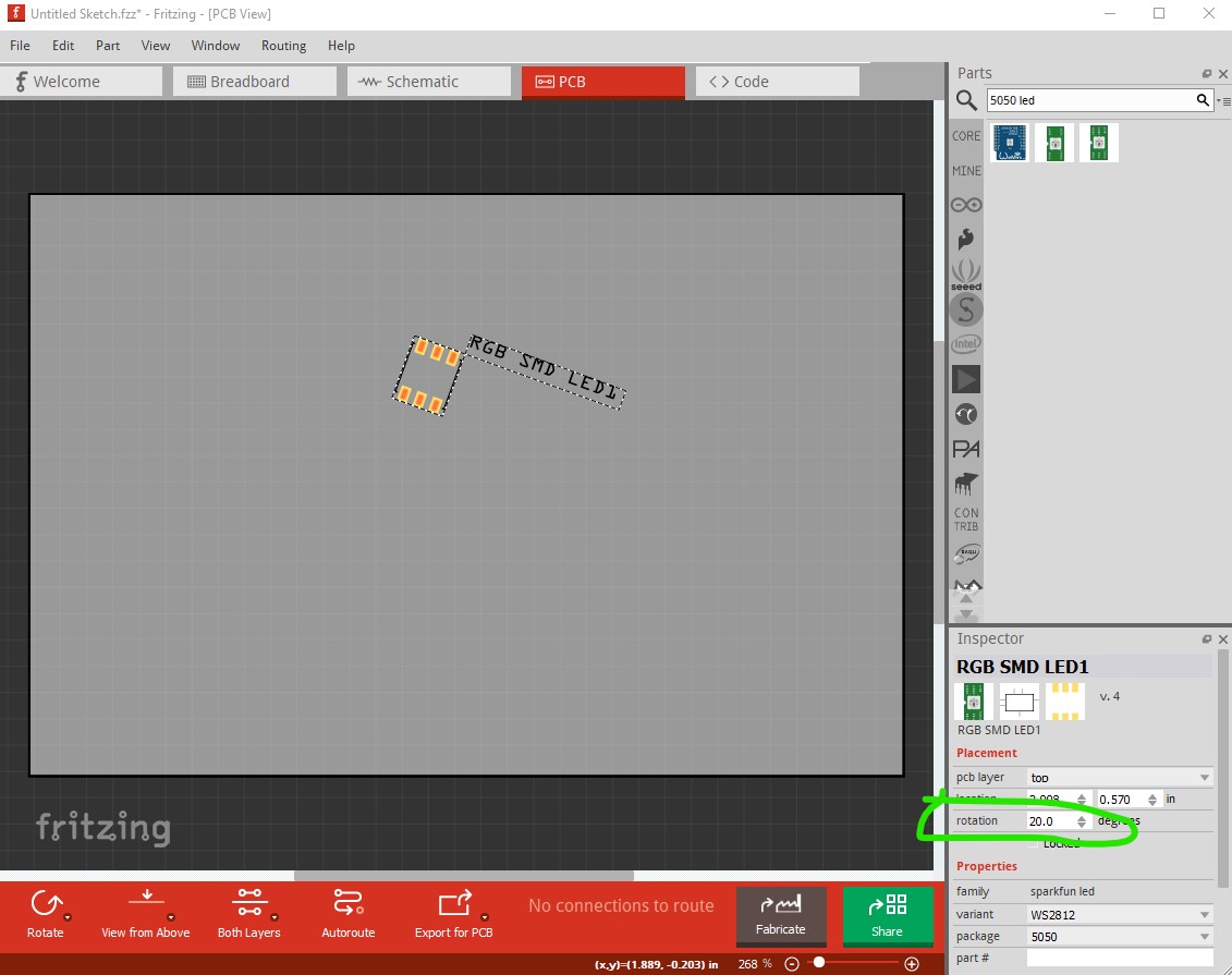
Here I selected led1 and zoomed out to the max. I then changed the X coord (in mm) by 0.01 intervals and recorded the set value:

x coord in mm

set displayed

51 - 50.997
50.99 - 50.997
50.98 - 50.977
50.97 - 50.968
50.96 - 50.958
50.95 - 50.948
50.94 - 50.939
50.93 - 50.929
50.92 - 50.919
50.91 - 50.910
50.90 - 50.900

here the value tracks pretty closely to those entered! This indicates that a partial workaround is set the values with the image zoomed in to the max! The zoom factor appears to be what is affecting the set values (indicating to me that the coordinates are in the screen representation and are having the zoom factor multiplied or divided to set the coordinate values which I believe is incorrect and causes the reduction in dynamic range!) because as the zoom gets smaller the values compress.

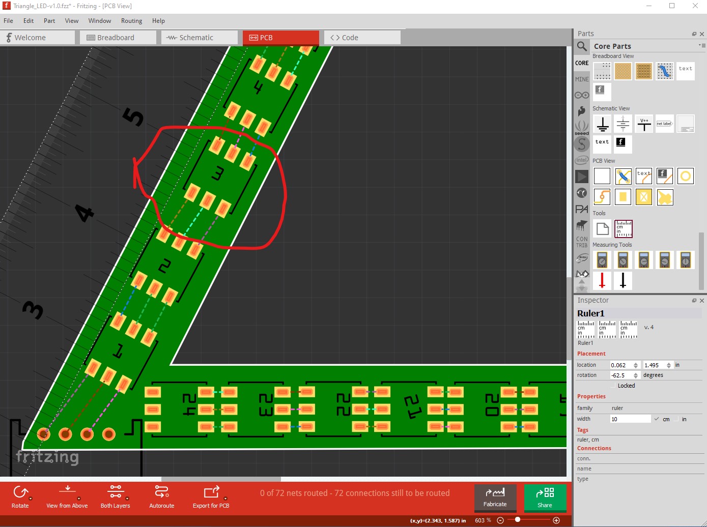
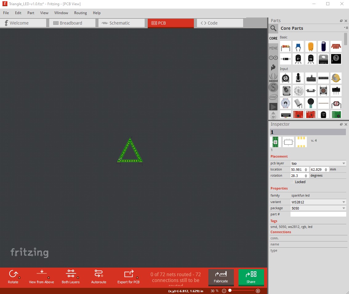
Here I zoomed out to show the full board in the screen and repeated the above

x coord in mm

51 - 51.021
50.99 - 51.021
50.98 - 51.021
50.97 - 51.021
50.96 - 50.900
50.95 - 50.900
50.94 - 50.900
50.93 - 50.900
50.92 - 50.900
50.91 - 50.900
50.90 - 50.900

note the much smaller dynamic range of values. Then I zoomed out even further:

and now the values are even more compressed.

x coord in mm

51 - 50.900
50.99 - 50.900
50.98 - 50.900
50.97 - 50.900
50.96 - 50.900
50.95 - 50.900
50.94 - 50.900
50.93 - 50.900
50.92 - 50.900
50.91 - 50.900
50.90 - 50.900

I think this should be fixable fairly easily by just changing from the zoomed screen coordinates to the actual values in the database which should make the coordinates correct! Of course as always the devil is in the details, but I suspect the image is rendered from the values in the database multiplied by the current zoom value and thus this change should be fairly simple.
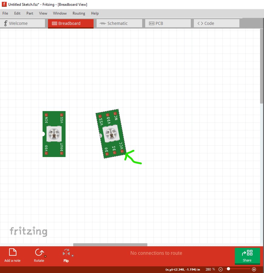
I would say at this point the next step is to decide what LED part you want to use and if it doesn’t currently exist then make a Fritzing part for it and then try the new (zoom all the way out) method for placement and see what the result looks like. I think it should be acceptable.

Peter

1 Like