Hello folks, I saw that there were the shottky diodes but I can’t find the DO-201 diodes going through. Would I have looked badly? Thank you in advance.
A google search for “fritzing part do-201” doesn’t turn up a part. Which means that unless one of the current parts matches the pcb footprint you need you will need a custom part (assuming you are making a pcb.) Unless you want one of the SMD variants, the generic 1N5817 should work, you can edit the part label by right clicking on it and selecting edit to change the name to D0-21.
Peter
1 Like
My DO-201 diodes are through. Isn’t there a way to easily edit parts without going through image editors? For example for the holes, one can easily change all sizes, thickness ect …
And yes, I have my cards made because I am very limited in material ^^
Then the default zener with a part number change should do what you need. It would be a good bet to check the gerber drill.txt file to make sure the hole size is large enough for your diode though. The default size is
; NON-PLATED HOLES START AT T1
; THROUGH (PLATED) HOLES START AT T100
M48
INCH
T100C0.035433
%
T100
X017911Y011777
X015111Y011777
T00
M30
0.035in (from the T100C0.035433) line in drill.txt file and a 1n4001 type diode is typically 0.042in. The current zener is obviously set for 1n1448 type small signal diodes and your part may not match that (it looked like the 1n4001 type in the data sheet, but I didn’t check the pin width!) However a further search indicates that the Sparkfun 1N4732A zener (also in core parts) has 0.042in holes and thus would be the one to use if your diode is indeed like a 1n4001.
Unfortunately at least at present, no. The parts editor was not completed when development stopped in 2016, now that development has started again there may be improvements, but not yet, bug fixing is currently taking all available time. I expect you will always have to use an svg editor for some parts, but some improvements should be possible.
Peter
1 Like
Erf >.< Je vais essayer de trouver un tuto en français alors  Merci pour vos explications.
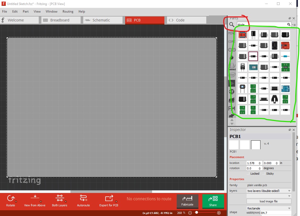
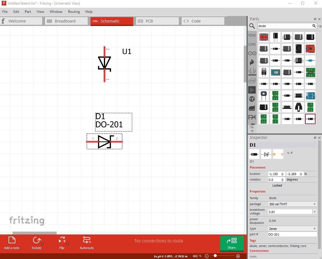
I’ll try and make this more clear (you can run it through google translate in to french if the english is a problem) because I’m not sure you will find a suitable tutorial. To start I did a search in the parts bin for diode (to find all the zener diodes that are available.) To do that I entered “diode” in to the search panel and hit enter (a mouse click will not do the search, only the enter key!) That brings up all the available diode parts in core parts:
Now search them one by one until you find the zener diodes here is the first possibility:
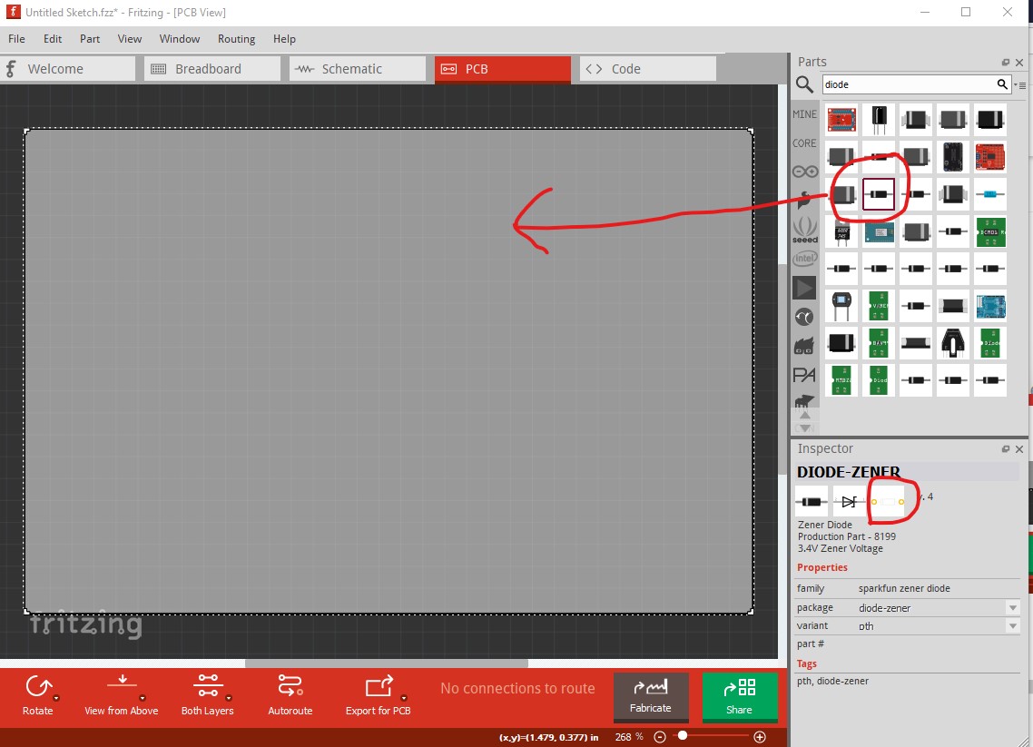
It is a possibility because in the lower right window we see it is a zener diode and (circled in red) is through hole in pcb. So drag that in to the pcb view.

There are a number of problems with this. The hole size on the pads is too small (these are 0.035in for small signal diodes), the part label should be d (for diode) not u (which is typically an IC) which is an error in the part, and there is no part number, although that isn’t an error as we can set one. Since we can’t change the size of the holes in an existing part, we need to look for another option.
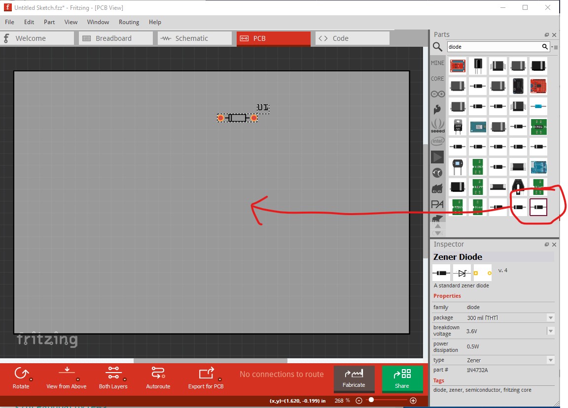
The only other zener diode in through hole is this one so drag it in to pcb to look at it.
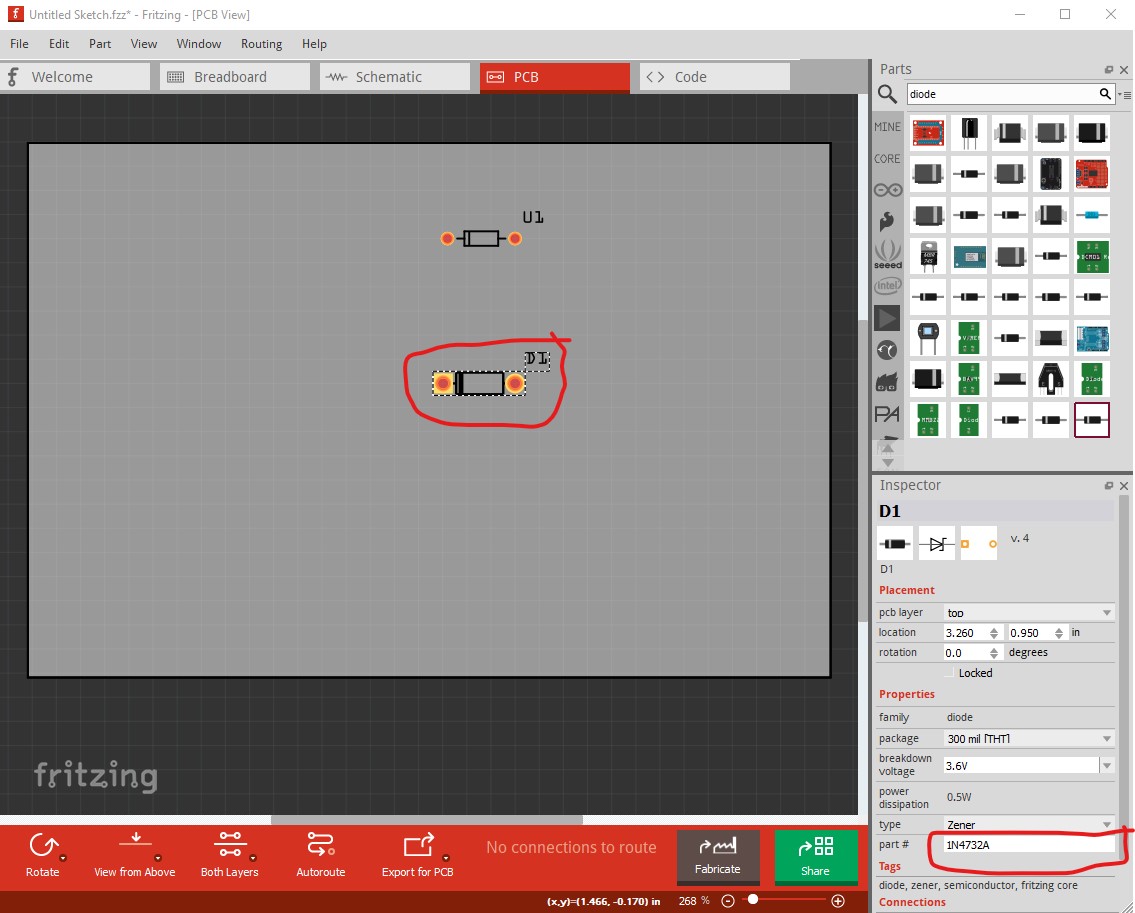
Here things look better. The pads are larger (and I already know the hole size is the correct 0.042in, although I will show you how to check that later.)
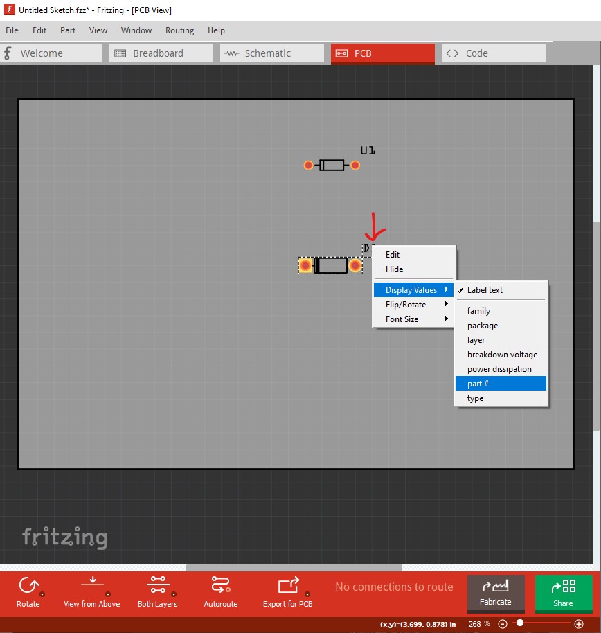
here I have right clicked on the label (D1) on the diode. That brings up these menus where we see the only thing selected is the Label text (D1) at the top. So click on Part # to select it and the part number will be displayed.
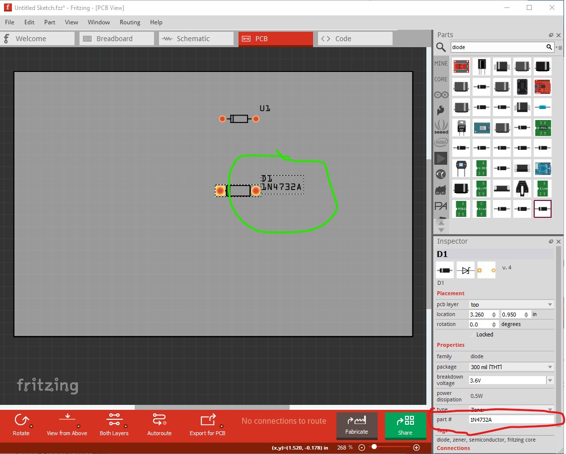
This isn’t the part number you need, but that can be changed in Inspector (the lower right window) to DO-201 like this:
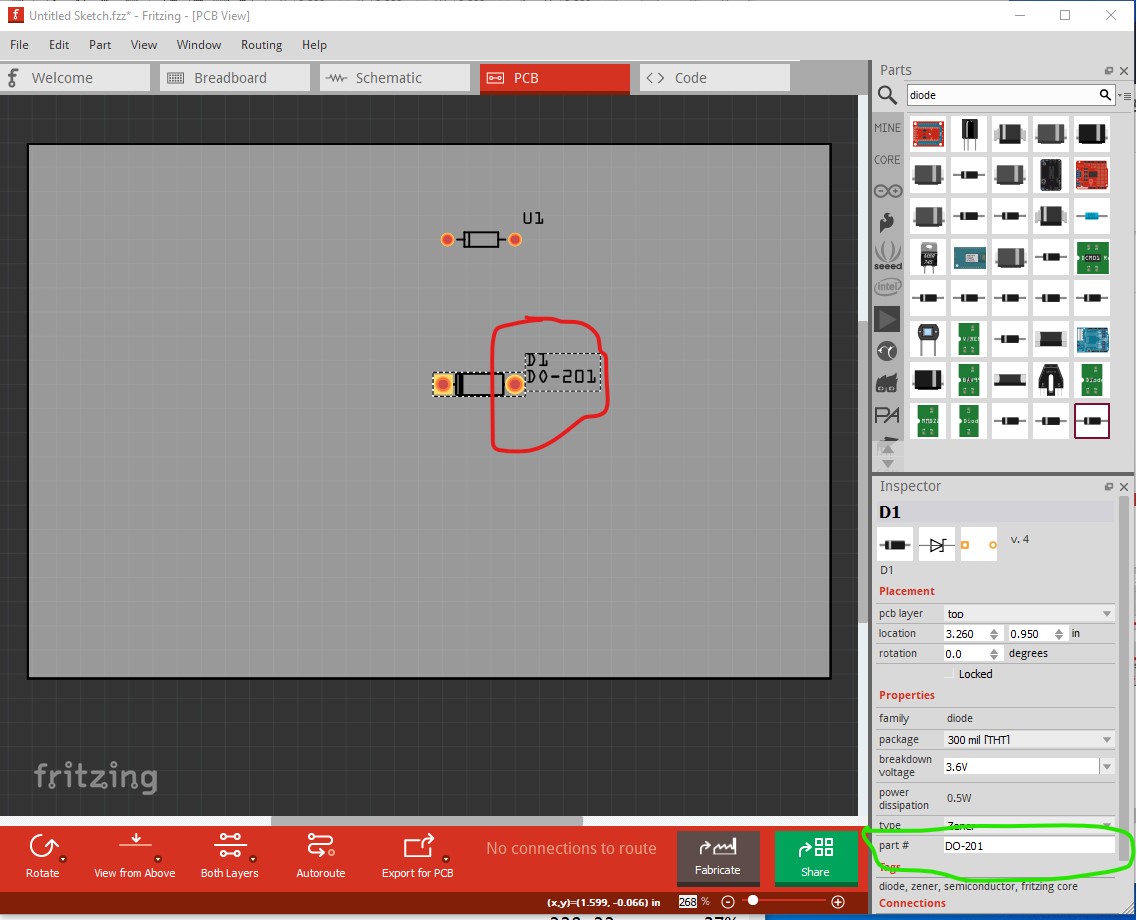
Change to schematic view and the diode now shows up labelled as D1 and part number DO-201:
again the part is somewhat wrong in that the ends of the pins are not on .1in boundaries, but it will work as is. Hopefully this is more clear than my last attempt  . Now I will demonstrate how to verify the hole size in pcb is indeed 0.042in as it should be. If you don’t intend to make a pcb you can skip this part, the procedure above should let you use the diode in breadboard and schematic. To verify the pcb hole size we need to export the sketch to gerber files (as would be done to produce a board.) To do that in pcb view select this
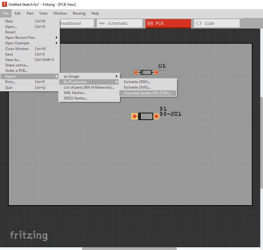
which brings up this panel. Here select a directory where you want the gerber files (d:gerber in this case) and hit select folder. That will write the gerber output files in to the selected directory which looks like this:

here we want the file Untitled Sketch_drill.txt so open it in a text editor such as notepad (notepad++ in this case):
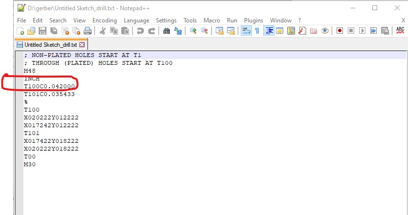
and here we see that the holes for the larger pads are indeed 0.042in as we need for the DO-201 diode, and the holes for the other diode are too small at 0.035in. The proper way to do this is to only have the diode we want in pcb view so that only its holes will appear in this file (I did that earlier.) Hopefully this makes more sense than the original post. If it still isn’t clear feel free to ask again .
Peter
1 Like
So I now understand how to check the size of the holes, thank you because this will save me a lot of surprises.
On the other hand I think I was a bit silly because I now see on my package that it is DO-201AD.
But I’m completely lost with these diodes it’s hellish I don’t even know if I should put an IN5820 or an SR506.
Suddenly I realize that it is useless that I bother you on this forum for the moment with this subject I am really but really sorry.
I am a beginner and sometimes nothing blocks me. >.<
Yes, a good thing to check especially with parts you find on the net (but even in core) as there have been cases where people ordered boards only to discover that the holes are wrong in the Fritzing part and the boards were useless.
That will be an issue here, the AD case is shown as .052in max pin diameter so you will need a custom footprint with larger holes (probably 0.058in) to fit that. As well the IN5820 is a Schottky rectifier not a zener so you would need to start from a Schottky diode part to get the correct schematic element.
That will depend on the voltage and current your circuit is using. The 1N5820 is rated for 20V and 3A continuous and the SR506 is rated for 60V and 5A continuous. The SR502 would be the equivalent of the 1N5820 if the current is the issue, but the SR506 will work fine as well. Basically the diode needs to support more than the voltage you have and more than the current you have. Higher is fine (but may cost more) but lower may destroy the diode causing the circuit to fail. Feel free to upload the sketch of what you are doing and we will give you advise on what to look out for.
Peter
1 Like
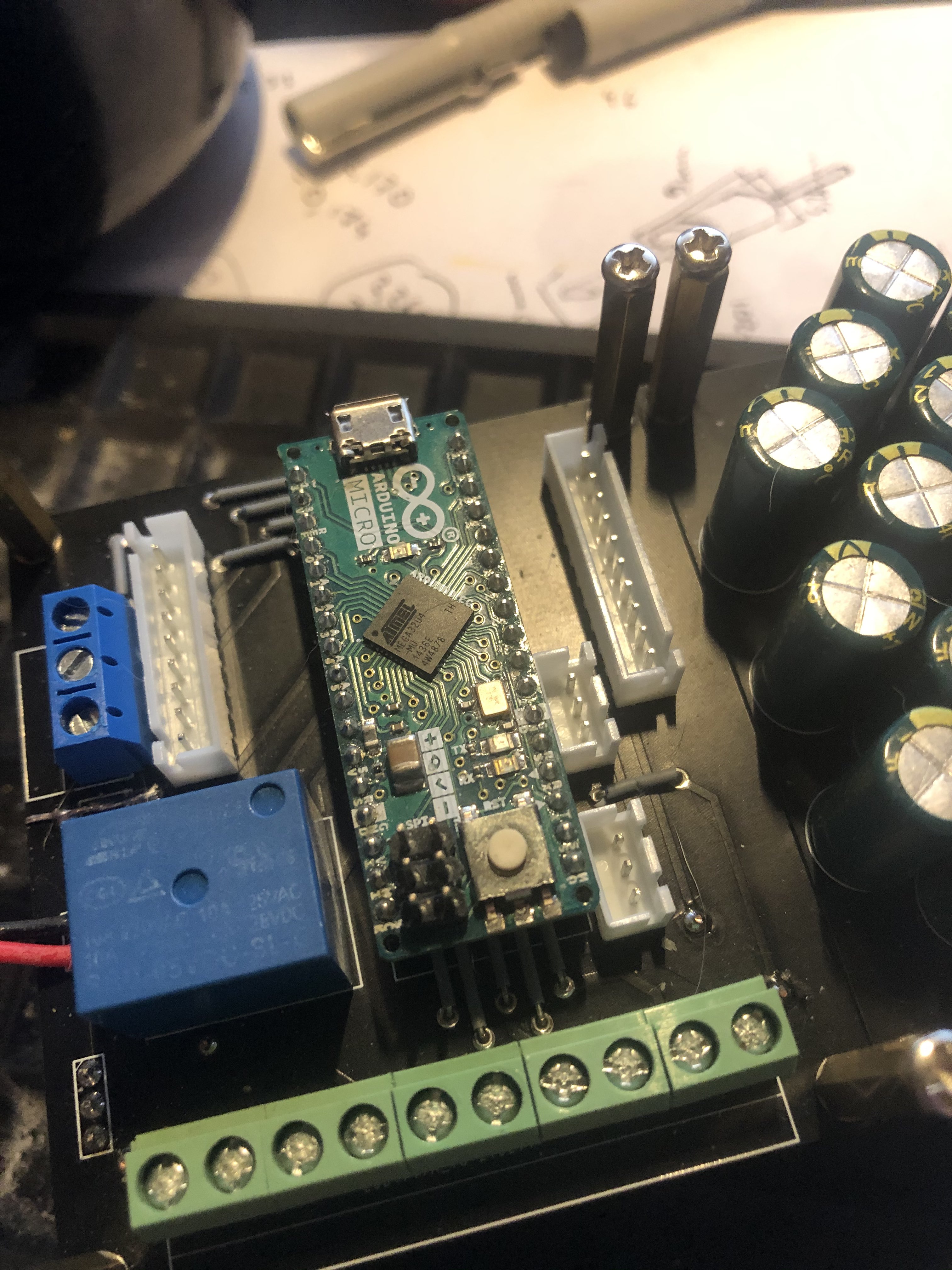
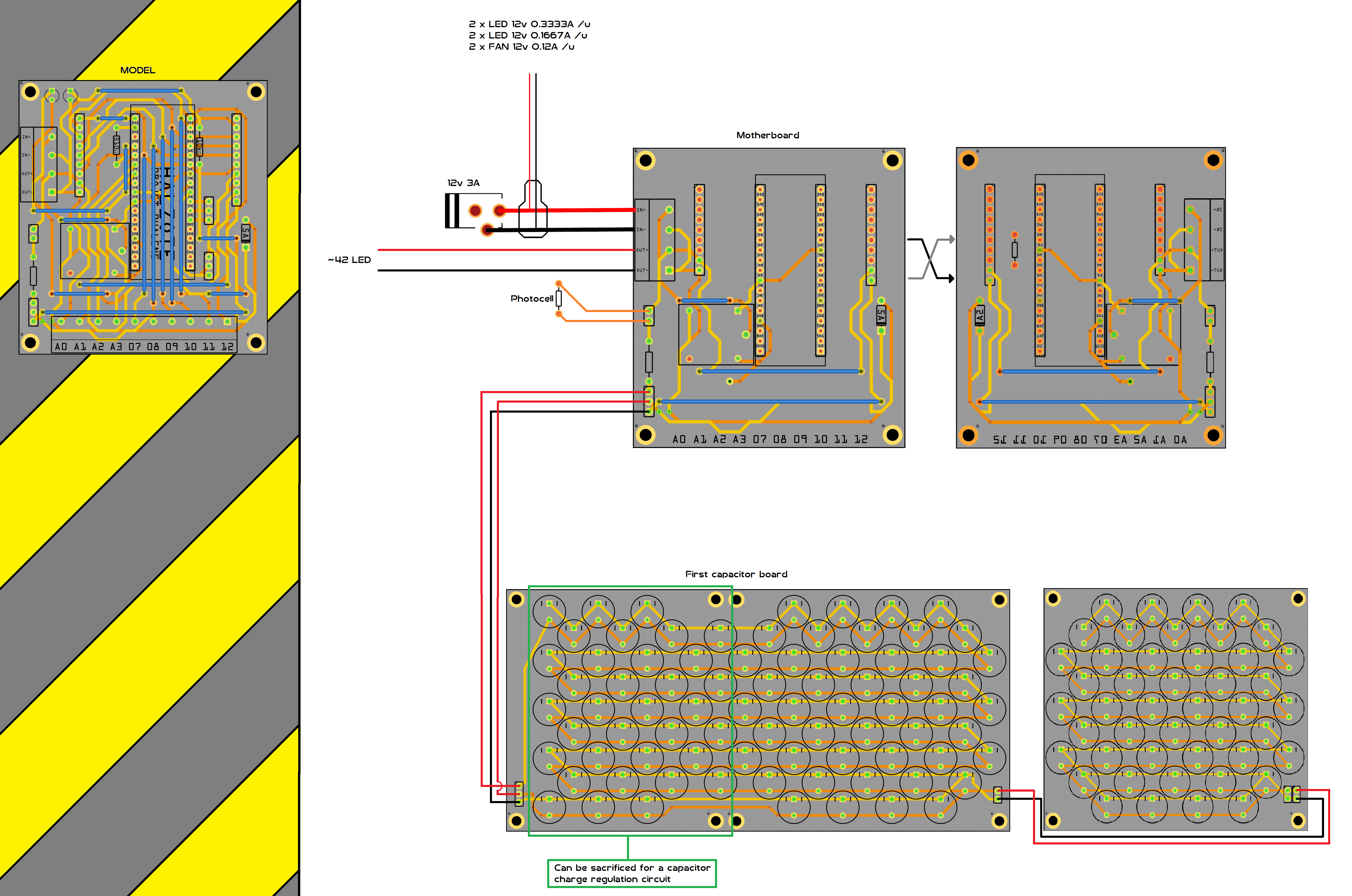
So it’s a bit complicated to show what I’m doing while remaining understandable because these are PCBs that fit on top of each other with an Arduino board.
But this part has the advantage of being a bit parallel to the rest of the project so I just simplified it.
There’s a lot more capacitor than that because it’s supposed to keep 42 LEDs on for a few more seconds after the circuit is turned off.
I use 3 amps because before the capacitors I need enough to power 4 12 V LEDs and three Noctua fans.
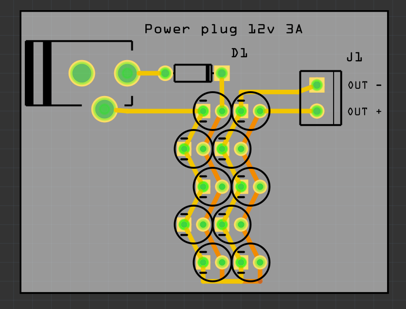
Finally here, in short, the DC electricity enters through the plug, passes the diode and feed my LEDs by charging my 16v 2200uf capacitor in passing, which should only be discharged
OK, a couple of things to consider. Hopefully the 12V 3A power supply is current limited to 3A, and if not you need to switch to one that is. The reason for this is that the capacitors when discharged will try and draw all the current they can get at start up, which will overload both the power supply and the current rating of the diode. If the power supply is current limited it will reduce the voltage from 12V to something lower until the output current is only 3A and the voltage will then increase to 12V as the capacitors charge. That has the effect that it will take the capacitors some small time to charge up to 12V (I’d expect under a second off the top of my head.) I would use the 5A diode so either the SR502 or SR506 would work (either easily supports the 12V in use, but 5A leaves some head room at 3A so the diode isn’t operating at its maximum rating.) The other thing you may want to do is increase the size of the traces on the board due to the somewhat large current. To do that select the trace
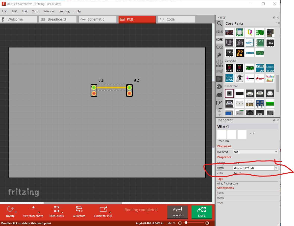
then in Inspector change the trace widh to something larger.
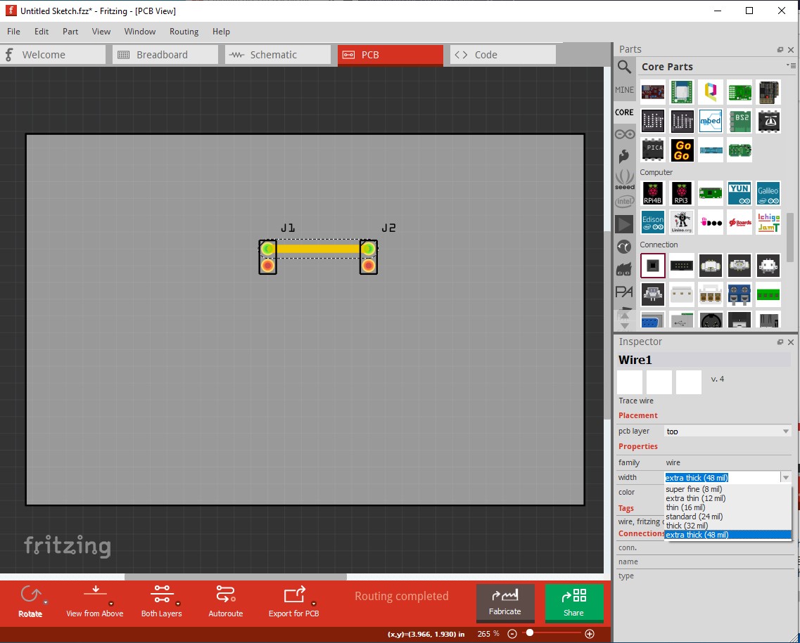
this reduces voltage drop due to resistance in the traces. In practice you can change the trace width up to as high as 999mils (almost an inch) by typing 999 in to the field (the pull down menu doesn’t go that high though.) In your case one of the pull down values should work fine, make the traces as wide as possible in the space available and there is a bug that larger traces tend to not connect to the pads correctly (although it may have been fixed in 0.9.6.) You may also need to check the current rating of the connectors. As I recall 0.1in headers have a maximum rated current of 2A, so running 3A through them may cause them to fail over time. You may need something like screw terminals which are typically available in higher current ratings (and again, you want something with a 5A current rating to leave head room at 3A.)
Peter
1 Like
Ok I didn’t even realize this kind of problem.
I only have that for information on my diet.
Is there any indication that you are not speaking?
I had already planned to draw the electric current for the fans and 12v LEDs before the capacitors.
So it would be enough just that I put a resistor before the capacitors to lower the tension to 2A?
And so I am thinking of taking the SR506 as I already have them because I prefer to play it safe even if it requires a higher kick. ^^
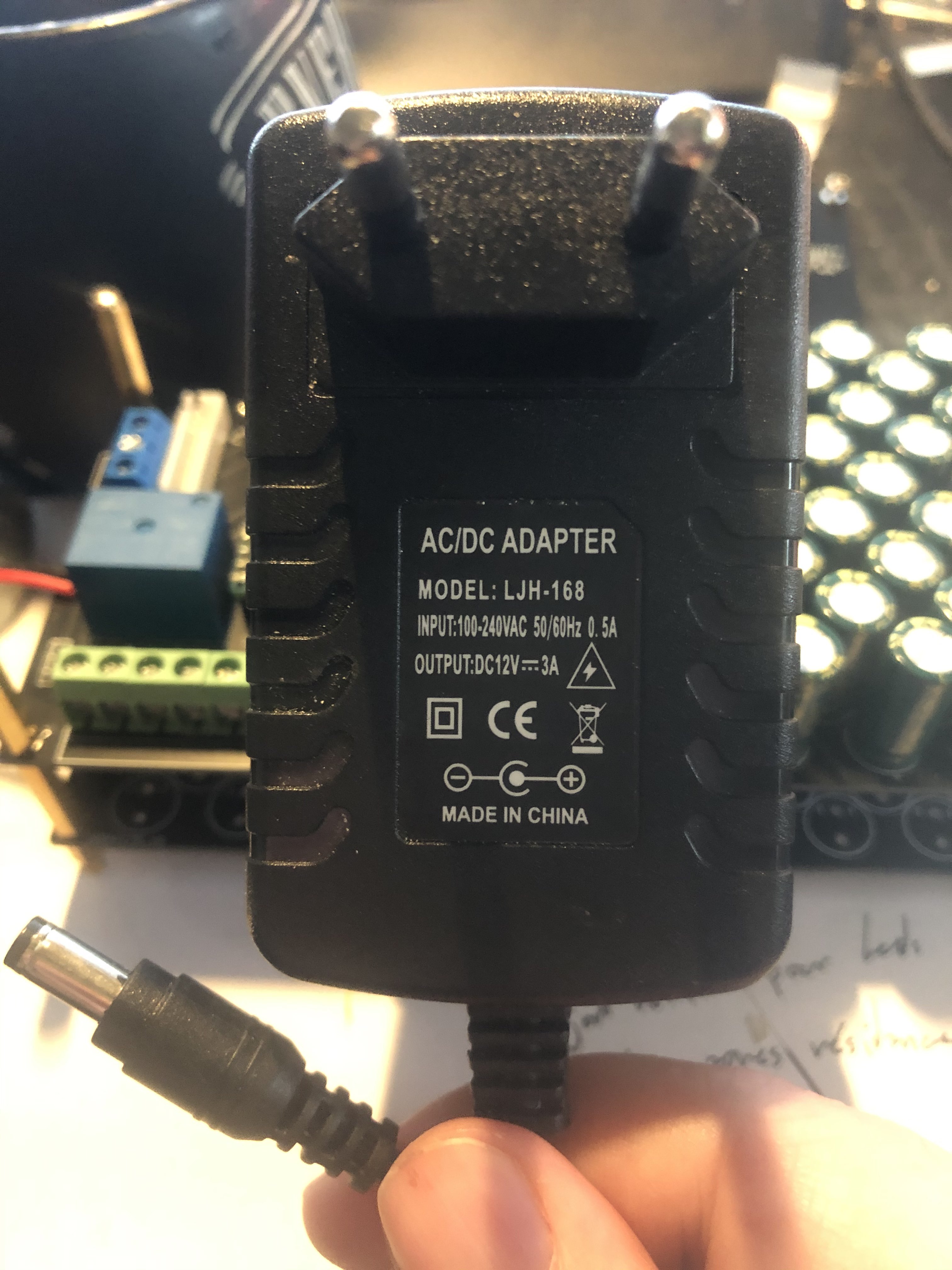
The power supply looks to be non regulated, and thus won’t current limit. A look at the SR506 data sheet here:
http://www.car-san.com/proditem_pdfs/doc_20110721164456.pdf
indicates here in figure 4 here
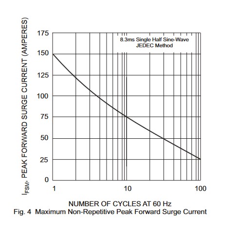
that it can take a large surge current for a short time (which should be the case here, the capacitors should charge fairly quickly I expect.) It should survive 25A for almost a second (and the power supply may not be able to supply that much current anyway!)
The problem with a resistor is that it is always there, and will drop the voltage seen by the load which is undesirable. The usual way I have heard of is to use NTC thermistors to limit the surge current. They start out with a high resistance (because they are cold) and reduce their resistance as they heat up from the current flowing through them. Another way would be to put a 5A capable coil in between the power supply and the capacitors (the coil has the opposite effect of a capacitor, it trys to keep the current constant and thus limits the surge.) The problem there is the coil is likely to be physically large (and possibly expensive). The easiest way is to just use the SR506 diode and hope the capacitors charge up fast enough to stay within the surge current limits. To that end here is a Fritzing part for a SR506 diode with the pcb pad holes set to 0.06in which should fit the pins.
edit: Replace the current part with one that has the pads spaced 0.5in apart (rather than the current 0.3in) as the diode won’t fit in 0.3in!
SR502-Schottky-Diode.fzpz (4.4 KB)
Peter
1 Like
How about this as an alternate circuit?

When power is applied (switch is closed, or plugged in), the LOAD will get the full 12V, the LEDs will get 11.4V (12V minus 0.6V drop for D1), and capacitor C1 starts charging through R1 towards 11.4V. D2 prevents power from getting ‘around’ the resistor to the capacitor. When power is removed. the LEDs will initially get 11.4V minus 0.6V drop from D2, falling as C1 discharges. Choose the value of R1 to limit the inrush current, to protect both D1 and the power supply. That initial surge (through D1) will be whatever current the LEDs normally use, plus (11.4 volts / R1). When fully discharaged, C1 acts like a 0 Ohm short. The power supply will see all of that, plus whatever is used by the rest of the LOAD.
Assuming the 42 LEDs plus fans and other LEDs use a total of 2A, R1 = 11.4 Ohm will keep the total current (for the power supply) to a maximum of 3A, and the current through D1 to 1A plus whatever is used by the 42 LEDs. A more common 10 Ω resistor would probably keep the power brick within tolerances. 15 Ω would be safer. Note that fans, being motors, tend to have a higher startup current than when running normally. So the numbers used for the calculations should be that starting current as well.
As I view the partial circuit from your image, it appears the capacitor would also supply power to the fans and other load. This way, it would only power the 42 LEDs.
1 Like
Good thought! This should do what he wants. If R1 is 4 ohms, the caps will charge (assuming they are discharged completely) at about 3A. You may want to use a 5W resistor for R1 as it may get somewhat warm. A 1 watt resistor may do, as the load should be short term.
Peter
1 Like
4 ohms at 11.4 volts would be 2.85 Amps, and just under 32.5 Watts. But as indicated, very short time, as that immediately starts dropping as the capacitor charges. The resistor would not have time to get hot. I would use a higher value resistor, with longer charge time, because that 2.85 Amps is in addition to the power being used by the 42 LEDs, the 3 fans, and other 4 12V LEDs. That 2.85 Amps is on top of whatever the rest of the circuit (without the capacitors) would draw on startup. And as mentioned, the fans could have increased startup current as well.
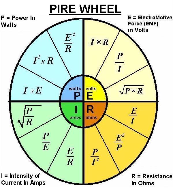
All of the numbers coming from ohms law and power law, which combine to create 12 formulas shown on a PIRE wheel.
1 Like
Hello, thank you very much for your answers but I admit I have a lot of trouble understanding them knowing that I am really a beginner and self-taught. Few notions I’m learning bit by bit and there for me you have literally gone to the other side of the mirror ahah ^^.
As it is very difficult for me to represent patterns, I would have to force myself more.
But above all I see that I was not clear at all and therefore I will try to clarify what I am doing.
To begin with, the four 12v leds will be used as lighting for the office so they will not always be on and the fans will be used for the radiators of the leds so will only work when the leds are on ^^.
Then I will add fans for me in the summer but even these will not always be on. And all this will be punctured before the capacitors.
At the top left, the “model” is my motherboard which I have purified in the center to only highlight the 12v circuit and that of the relay. The relay lets current flow when the PIN 2 of my arduino board is connected to GND.
The capacitors are only there to allow the LEDs to extinguish very slowly after the power is removed. There are 42 LEDs but I plan to add more to the assembly.
Thank you again for your help. She is sincerely appreciated.
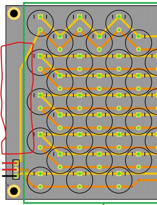
I just noticed another potential issue: the diameter of the capacitor in silkscreen is (from the pcb svg file) 8.2mm, when I looked up a 2200uf 16V capacitor on digikey the case diameter is 13mm, so much larger than the circle in pcb view. So you need to check the diameter of the capacitors you are using to make sure they will fit in the board as expected. The diameter of the case in silkscreen for generic components such as capacitors isn’t necessarily representative of the real part, because they are intended to be generic and you need to adjust the spacing to match the actual parts you are using. The two diodes and the resistor should fit on the end of one board (in the red circle here) without problem, they aren’t that large.
Edit:
I just had a thought of another way to do what you want that is more flexible and doesn’t require the capacitors.
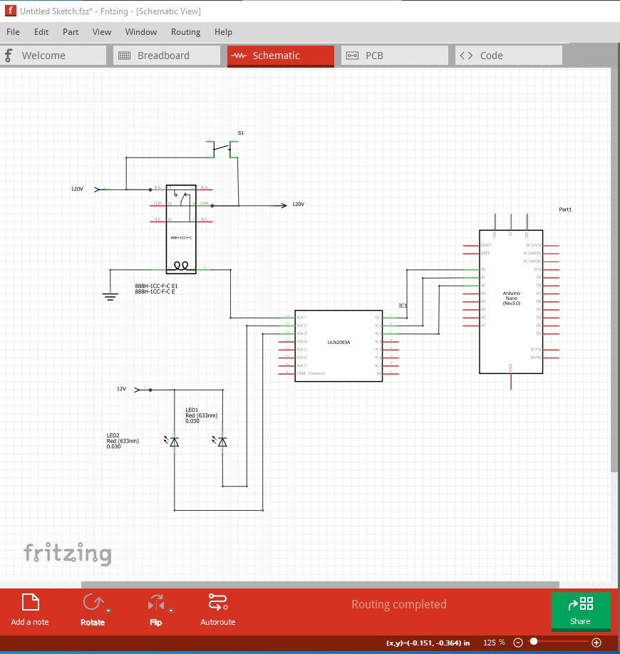
Here the relay switches the 120 (or 240)V power to the power supply. A push button switch connected across the relay when pressed powers up the micro and the first thing it does is activate the relay (so power is still on when the push button is released.) The micro drives the LEDs, fans and what ever else is needed through high current drivers or relays. Now timing of shut down is in control of the micro processor. It can shut off everything except the LEDs, then wait a programmed amount of time (which can be easily changed unlike the capacitors) before deactivating the relay which shuts off the power and shuts the whole circuit down. I don’t have the part for the power supply handy so I left it out of this drawing, but it connects to the 120/240V input power from the relay.
Peter
1 Like
So I still do not understand the diagram ^^ And suddenly I will have to reverse everything because in the green square is the exit. But I can adapt.
For the Arduino board it just won’t be possible because all the outputs are used. Here is the code I wrote if you are interested.
https://drive.google.com/file/d/1j3ZZ7BkMNL1d7sX_RaVQ3ebKXmbMceb_/view?usp=sharing
But for the two diodes you are telling me about, would it be possible to have the montage under the visual of the program so that I understand better please?
Could you please upload the sketch (the .fzz file) for the motherboard (upload is the 7th icon from the left in the reply menu.) From the image above I can’t see where the capacitor banks connect to the LEDs. As well I think a large number of your jumpers can be eliminated by better routing on the pcb. With the sketch I can trace wires in Fritzing.
Peter
1 Like
Ahah yet I liked my routing me 
Catre Mère.fzz (51.6 KB)
These are the terminals that I use (this card did not work I had made errors which have been corrected)