Hello, I have a problem with the copper levels. So I am a beginner. I have made a 4-digit 7 segment display into a 2-digit one. I didn’t do anything to the PCB other than remove unnecessary connector and resize.
Now I get the message “This version of the new component editor cannot handle separate copper0 and copper1 layers”.
As I said, I didn’t change anything on the layers and I compared everything with different tutorials and everything seems to be correct.
If you upload the .fzpz file for the part (upload is 7th icon from the left in the reply menu) I’ll have a look at what is wrong. This tutorial on making parts may help as well:
as it details what the parts editor is looking for in terms of groups. If the original part had separate copper1 and copper0 layers (which is supported but not by the parts editor), the problem may be that Inkscape (as one example) will remove the duplicate connector names which will then break Fritzing.
edit:
Indeed the fzpz file indicates that separate copper layers are likely your problem. Here is how to fix it (this uses Inkscape, but the same should apply to other svg editors):
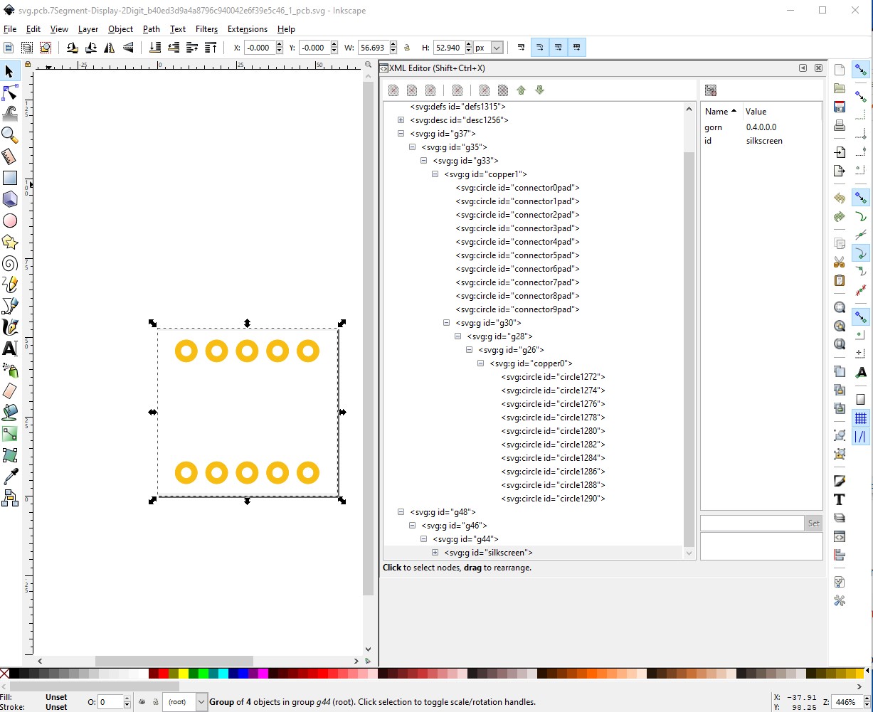
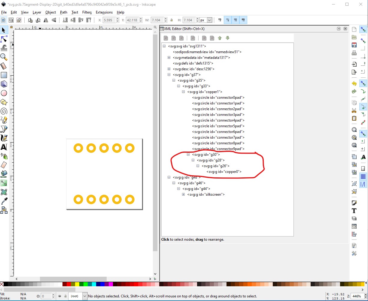
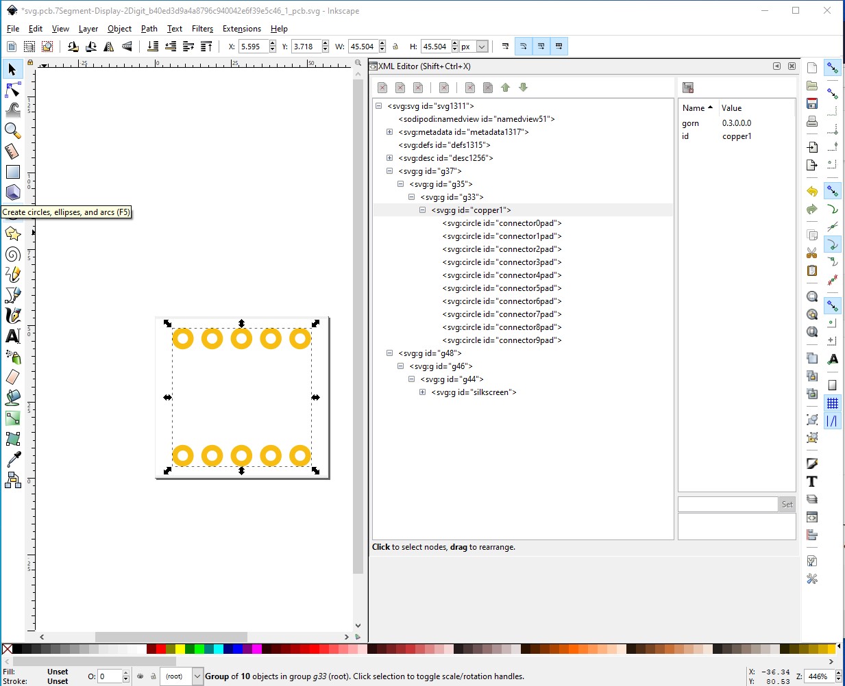
here is the problem: copper1 and copper0 are on the same level in which case the copper0 connectors need to be named connectorxpad the same as the ones in copper1 (which Inkscape won’t allow.) You can either edit the svg file with a text editor and change the labels every time you edit the svg (which is a pain) or switch to the more modern layout by first deleting all the pads in copper0 leaving only the groups:
Peter can have a look at the part, but just from the description the problem is (started as) that the original part was structured in a way that the Fritzing allows, and probably works fine with, for using, but that the current version of the parts editor does not handle. Specifically, through hole parts have 2 copper layers, for top and bottom. Each of those requires an id in the svg file, to associate the graphics with the connector. The current way to do that, that the parts editor supports, is to put the second layer inside of the first, so that the id for the connector only exists in the file once, but is still on both layers. The way that part was created, the copper layers were separate, and the connector was created in each. Which parts editor does not handle.
yes, that worked. Thank you very much. I used the more modern version and also Inkscape. Yes, there was probably something generated in the xml file that I didn’t catch . With the graphic solution I had the group arrangements also already in such a way, but that did not want to work. OK again what learned . Thank you.


 . With the graphic solution I had the group arrangements also already in such a way, but that did not want to work. OK again what learned
  . Thank you.