Hello, quelqu un peut il m aider ?
A chaque fois que je crée un composant sous inskape et que je le place dans le PCB fritzing mon composant a un rectangle de couleur hors quand je le crée je n en vois pas ?
If you upload the .fzpz file of the part that is broken one of us will have a look at it and tell you what is wrong. Upload is 7th icon from the left in the reply menu.
Peter
via google translate
Si vous téléchargez le fichier .fzpz de la pièce cassée, l’un de nous l’examinera et vous dira ce qui ne va pas. Le téléchargement est la 7ème icône à partir de la gauche dans le menu de réponse.
Hello,
thank you for your great responsiveness.
In fact my problem when I create the component starting from a component already created in the “PRINTED CIRCUIT” part everything is ok
But it is once I am on the global pcb that my rectangle appears, whatever the component I create.
I spent hours on tutorial, video and nothing to do.
I need the components:
- uPesy ESP32 Wroom Devkit
- DFR0745
Is it possible to buy these components By donation or other in order to dispose of them?
Cordially.
If you upload the sketch file (the .fzz file) I can probably tell you what is wrong with your part. There isn’t much information on the uPesy ESP32 Wroom Devkit to make a part ( a quick looks says it is different than the ESP32 modules I have Fritzing parts for.) To make a part we would need the dimensions of the board and they don’t appear to be on the uPesy web site. The DFR0745 isn’t that hard and I should be able to post a part in a bit.
Peter
A big red rectangle is usually and indication that there is a problem with the connector definitions. There is something not matching between the information in the fzp file and the information in the svg file for the view.
For the uPESY ESP32 the dimensions are 47 mm * 27 mm
and it has the particularity of having 32 pins unlike the classic esp32
Hello micromerlin,
You are right !
by dint of gallery I had not seen the message telling me that pin problems appear on my svg views.
But I do not have to understand the operation of the creation of component because I start from an existing component I remove pins not useful to me then I save, at this stage everything is ok but indeed I had not paid attention to this message .
I have therefore come back to square one.
This tutorial may help you to figure this out:
I don’t normally use parts editor, rather edit the underlying files which this describes.
edit:
Here is a part for the DFR0745. Feel free to post the .fzpz if the ESP gives you problems and one of us can fix it up for you.
dfr0745.fzpz (16.8 KB)
Note the part has a bus (an internal connection in parts editor) on the two ground pins and the mounting holes in pcb are only on silk screen. If you want mounting holes in the sketch drag the hole part over the hole in silkscreen to drill the hole. The reason is you can add the hole in the sketch, but you need to modify the part to remove the hole if it is in the part.
Peter
1 Like
Hello,
Thank you very much for the parts of the voice module! The reactivity and mutual aid is really impressive on this forum!
Days and days to look if my ESP32 uPesy could be available and I found for those that interest here:
uPesy ESP32 Wroom DevKit.fzpz (58.3 KB)
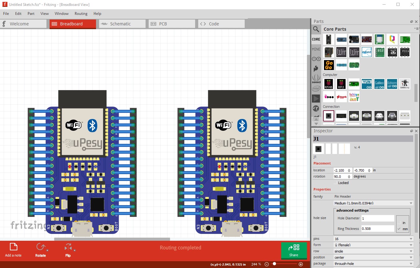
They did a pretty good job, but there are a few errors. Feel free to tell whoever you got the original part from they are welcome to replace it with this fixed one. Breadboard lacks the breadboard layerId (and thus won’t export as an svg from Fritzing) as well it is dimensioned in px which can cause scaling problems. In this case it is fine in Fritzing (as it looks to have been done with 90dpi Inkscape) but needed to be rescaled to be correct in the latest inkscape (which is 96dpi.)
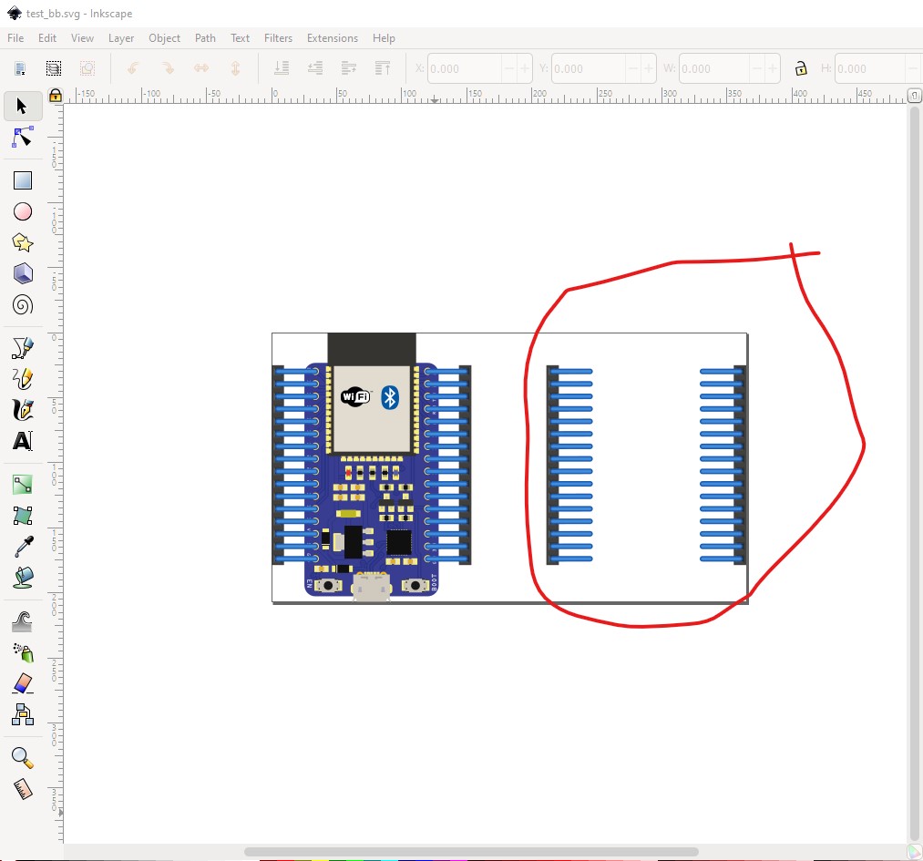
My corrected part is on the left in these images, the original (which has a new moduleId and thus will load alongside the original) is on the right.
and bb exported as an svg and displayed with Inkscape:
schematic lacks terminalIds and has wrong font sizes and colors (I replaced schematic entirely with an new one!)

The connections terminating in the middle of the pin is a result of no terminalId in schematic.
pcb looks fine in Fritizng
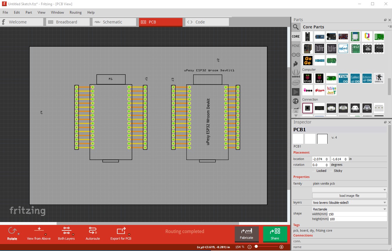
but when exported as gerber files and displayed with gerbv shows a number of problems
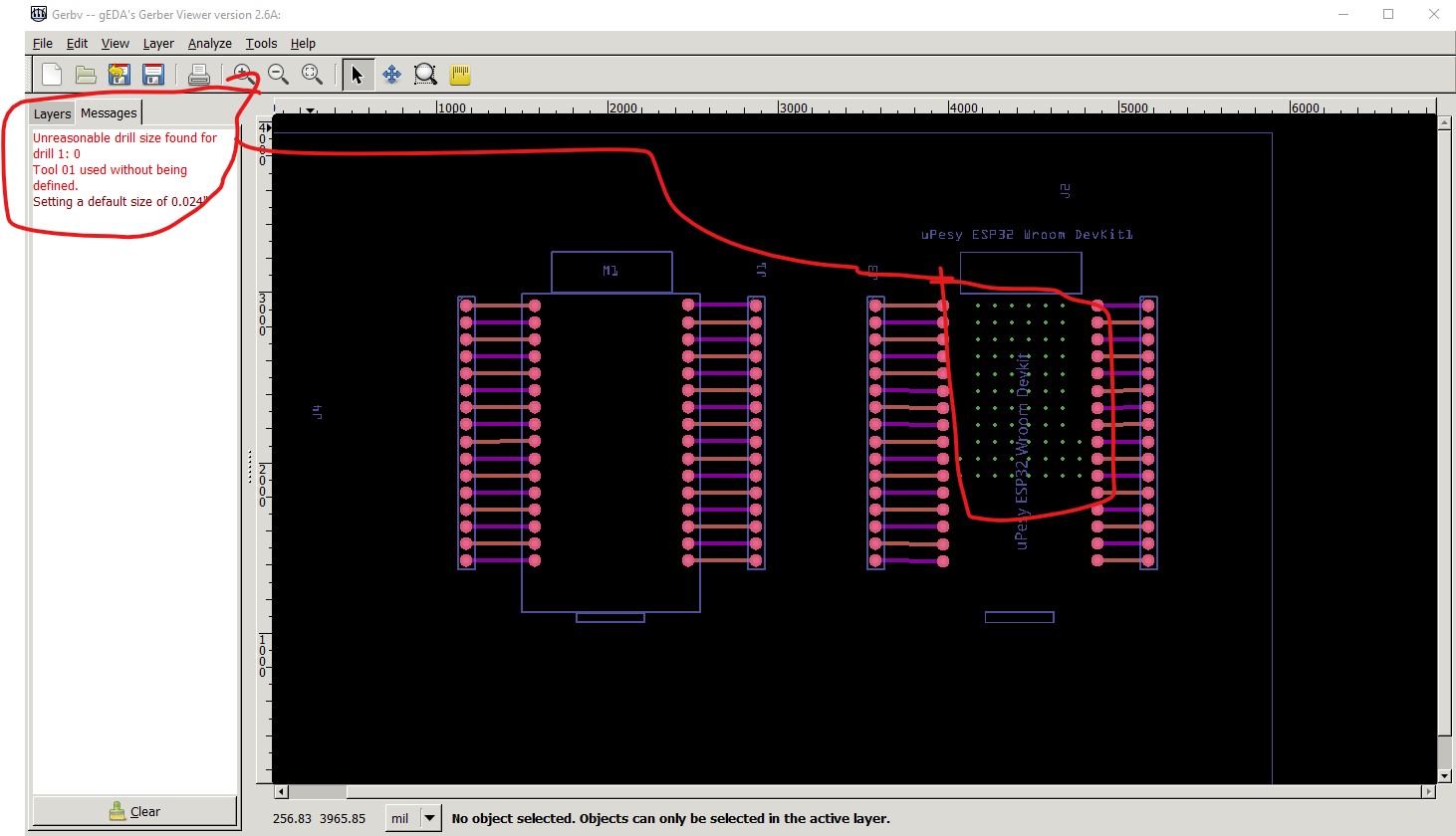
There are a number of unneeded holes (which I removed) that are set to a drill size of 0. Gerbv chose to replace them with a 0.024in hole which produces unwanted holes. I’m not sure what a board house would do, either declare the gerbers broken and not make boards or perhaps drill unwanted holes like this. In the fixed part the hole are 0.038in suitable for .1in header pins. Here is a corrected version of the part.
uPesy ESP32 Wroom DevKit-improved.fzpz (39.6 KB)
Peter