I am designing my second board, and as always appreciate if you can review the design. I am trying to make a simple temp sensor board connected to Wemos D1 Mini [ ESP8266] and have sleep mode on it. The battery i am using is 18650 li-ion style. There are a few areas that i am not sure of, so i would greatly appreciate if you can validate them.
PLACEMENT OF BATTERY HOLDER:
I want the bat holder to be in bottom layer of PCB, so that my overall WidthXHeight of PCB is small.
However, note that the Wemos (top layer) PINs need to clear the holder. I know this is possible because i have a prototype that i made exactly like this, and it works.(see pics)
The challenge i have here is, i am not able to move the Wemos “finely”. It seems to “SNAP” into locations, and hence, the pins interfere with battery. How do i move the wemos finely so its pins DO NOT go into the battery holder in bottom layer.
SWITCH FOR SLEEP:
I used a basic switch from fritzing panel. Basically, if D0 and RESET are connected (SWITCH ON or CLOSED), then i can program the Wemos to go into sleep mode, and wake after predefined time intervals.
a) I want the SWITCH to BE ON by default. I do not know, what PINS in the switch are ON by default. Currently, i have D0 connected to switch center [pin2] and RST to [3]. But is this CLOSED [ON] or OPEN [OFF], i do not know ?? ( i think it is)
But i think the real question is, --> is the part i chose for switch a slide type. If i move up, then it should connect “CENTER” and “TOP” i.e. D0 and RST. Is this what will happen with my choice of switch here.
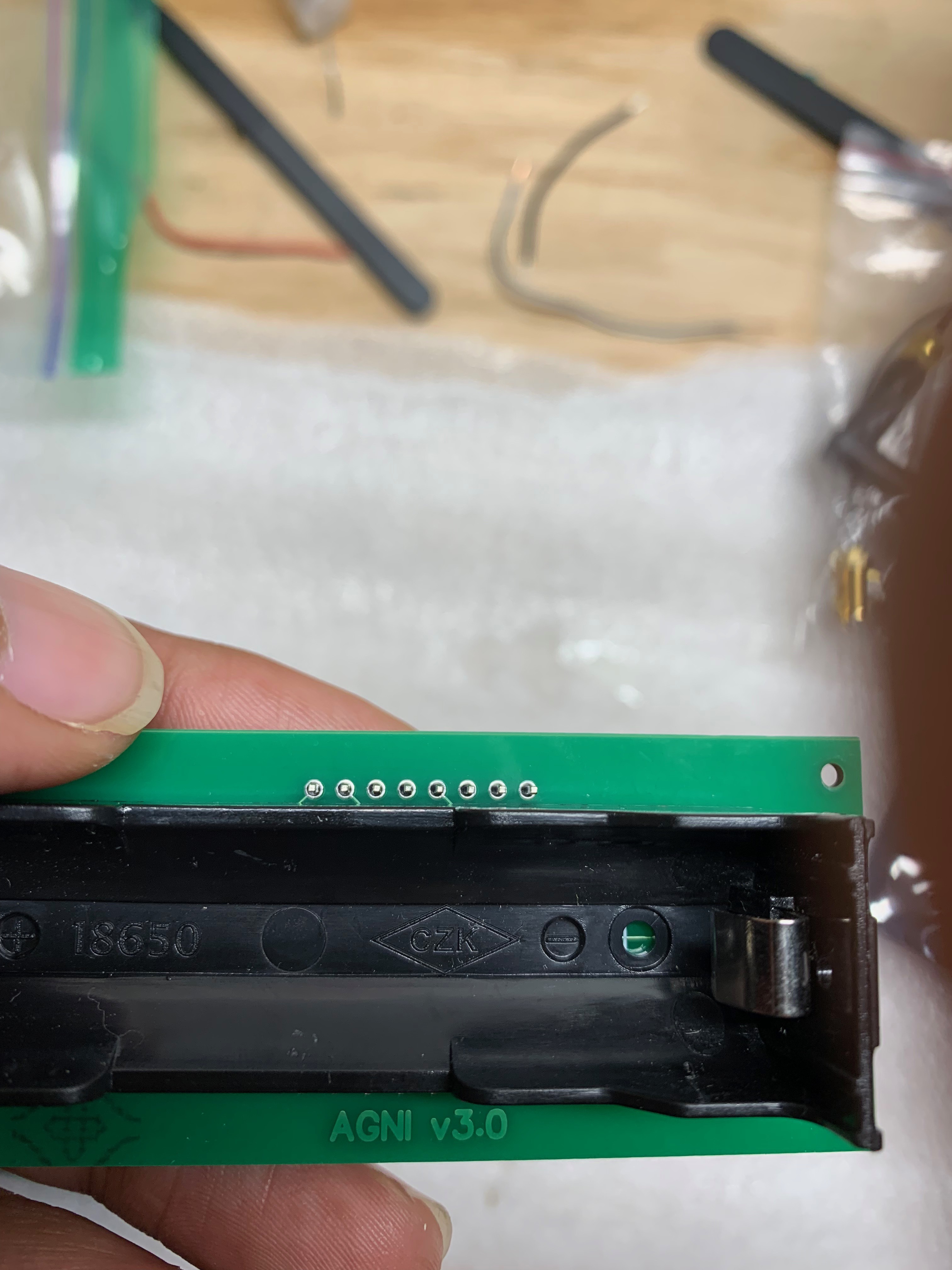
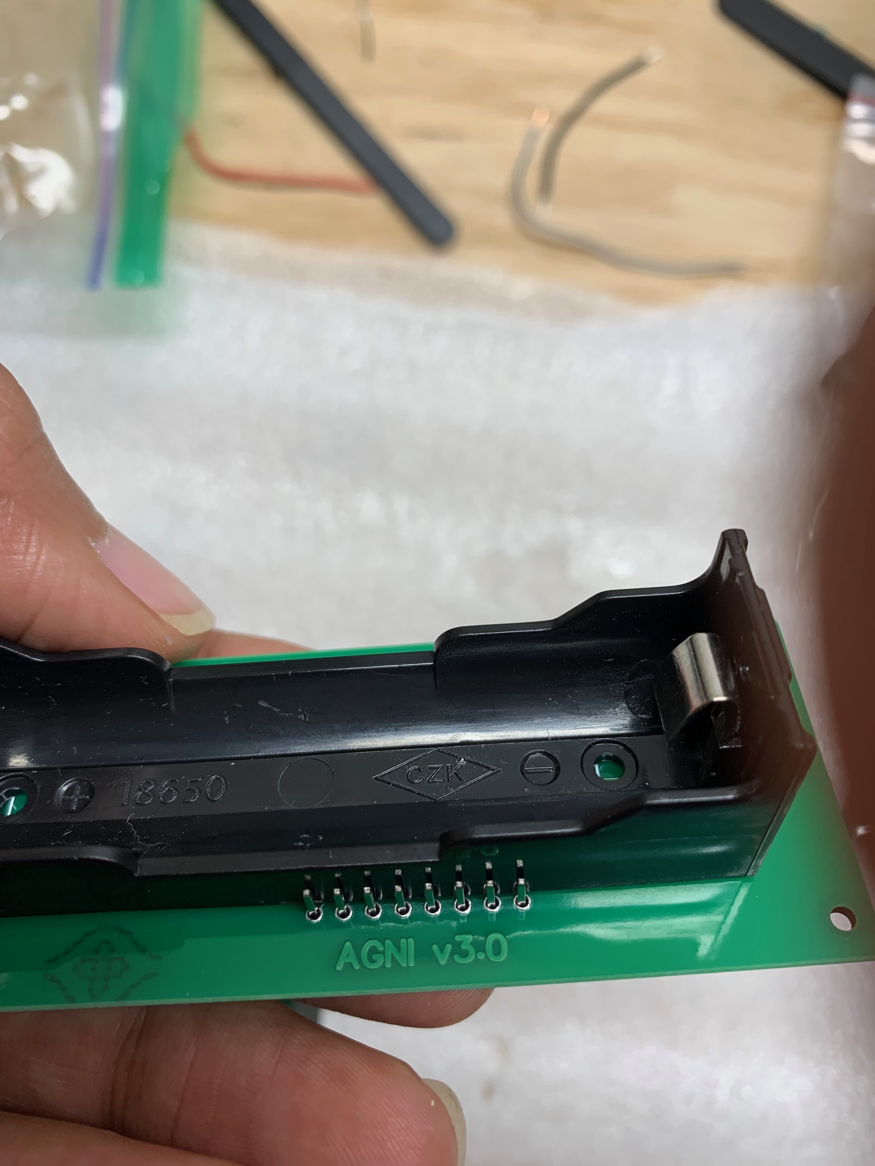
A couple of comments here, be careful with the 18650 battery. Most of the individual cells do not have battery protector circuits (they assume you will add this in your battery pack) and are thus dangerous if shorted (they tend to explode when shorted). They also don’t like being discharged to far (around 2.4V) however the ldo should take care of that as it will drop out at 3.3V). They are also reported to not work well on the older model Wemos boards (the ldo had a higher drop out voltage). You would probably be best with the Wemos battery shield which appears to be designed with these limitations in mind.
Yes the pull up resistor is correctly connected to pull up to 3.3V. Note your ground connection in breadboard view is not properly connected (thus the rats nest line).
In View unclick the align to grid box and it will stop snapping to the grid. You can also reduce the grid size from the default .1in to something smaller although Fritzing will slow down with very fine grid sizes.
Fritzing switches are generic (I remember making a NC one for someone some time ago though). It doesn’t really matter in fritzing, what matters is the real switch you are going to use and which of its pins are the NC pair and that it is a NC (normally closed) switch. The switch you use also must match the pcb footprint that Fritzing used.
edit:
What I would do is buy one of these:
and swipe the circuit board out of it. It charges the lipo battery from a usb port (any source of 5V will do) and has a boost regulator which provides 5V from the battery (I assume it also shuts down when the battery gets too low). That way your circuit will run longer than til just when the battery gets less than 3.3V and don’t need an external charger. If you don’t want the USB portS I assume you could unsolder them.
Thanks Peter.
Infact, the electronics will be enclosed inside a Rectangular box.
So i like the idea of using the Powerbank. In fact, i will just super glue it directly inside my box, pop a 18650 battery inside powerbank, then run a micro-usb (male to male) cable into Wemos usb port directly. That should power the main circuit.
HI Peter
I was trying to find the part for '18650 Battery Shield ’ on fritzing but couldn’t find one. Is there a way to import this part on to fritzing or any alternative to get the correct dimensions on to my PCB.
Can you please suggest as any wrong dimensions would make the entire PCB unfit to use.
I have gone through the below link and got the information for 18650 Battery shield.
Yes, I concur with Old_Grey.
Its the hole size and center-to-center distance that we are in need of.
I have these shields on order, and will update once we receive them.
Till then, the only option I can think of is to just plan for outside dims in the BASE PCB.
Then manually drill holes in the BASE PCB (based on hand measured hole centers once BATTERY SHIELD arrives). Then use standoffs to mount BATTERY SHIELD onto BASE PCB.
Peter,
That would be great. I was examining the part closely, and noticed from PICTURES that these holes are “pretty close” to edges.
I hate to approximate distances being a Mechanical Engg, but gut tells me, if they are M3 holes, then i would add 0.5mm on either edge, and add M3 radius, to get to a hole center.
But thats an idea . Once the physical parts arrive, we will know for sure.
ALSO if you are considering making the part: there appear to be two versions. The one i am interested in is
as the usb port is on the long side, and this suits us well.
I did a new sketch ( more of a dev board style) …can you please cross check.
I put a placeholder for the battery shield based on its dims (96x29) and guessed they are M2 holes.
I do have a few questions.
a)
I have 2 wires going to GRD. I think there is a better way to make ground connections. Any suggestions. I remember using a copper layer, but i dont know how you manage mounting holes ( 4 in corners).
b) I usually wire while in PCB View. And then when i goto Breadboard view, i see dashed lines.
and when i click autoroute in PCB view, it really doesnt do anything. Am i doing something wrong here. But it does autoroute, if i wire in Breadboard view.
The rule of thumb by pros is to not use autoroute - AR doesn’t even do a good job on 10K software -, but manually snap everything to the grid.
The reason you can’t AR is because you can only AR ratsnets. Your PCB has solid tracks, so you can only AR SCH view. If you put permanent traces in SCH, you can AR PCB.
I did all of this manually.
Holes in Arduinos are for M3 screws, so the holes are probably 3.2mm.
Remember to thoroughly check your design before manufacture, ie print out the gerbers and place parts on it. Also check it in a gerber viewer so you know all the holes are actually there.
Your number came up in the part creation lottery. As a result here is an almost part of the requested Lipo battery shield. It is an almost part because the dimensions were taken from one of the off square photographs on the Satisfy web site and are thus likely not very accurate. When you get a part (which may be pretty quick, Satisfy ships from a local warehouse at least here in Canada in a couple of weeks usually), and can take measurements and figure out what the two unlabeled mystery pins do, we can convert it to a real part.
I’d say you are likely to have exciting times with this. There is no apparent data on the net about these so you will likely have to trace leads to the IC pins to figure out how it works (Satisfy and all the rest typically ships just the part, no data on how to use it …) there are a number of connectors whose purpose is unclear (but they don’t connect to the pcb so I didn’t much care ). I hadn’t seen these so I’ll probably buy a couple the next time I’m ordering something.
Hi , i have been looking for a solar panel and charging module TP4056 Part so that i can charge my battery through the solar panel and get a long life for but not able to get one .below are the links to get them and their dimensions.
In general the place to start is google. A google search for “fritzing part TP4056” turns up a variety of hits. The first one (AchimPieters) is not the correct model, but in the images section we come across this one (which I don’t remember doing ) which does look to be the correct part (use Old_Grey’s corrected version):


 ). I hadn’t seen these so I’ll probably buy a couple the next time I’m ordering something.