Hi there.
I need 2-row headers with numbering as used for RPi’s and Zigbee modules etc, i.e. numbering in a zig-zag pattern.
Although discussed here for many years, I couldn’t find a solution for my need. Neither a generic solution or specific components with 12 and 14 pins and the right numbering.
Any tip and/or advice would be appreciated. Is there for instance a way to manually edit the fzp foles to change/correct the numbering? …as a solution until the numbering scheme is added to the generic component as option.
I appreciate the “backward compability issue”, so adding an extra option into an existing component is perhaps not doable, but would it then be possible to have another generic header with the zig-zag numbering scheme adopted?
You likely need custom parts. There is one for the 40 pin variant but I don’t see a 26 pin version. Normally I would make you one, but I have strained my wrist and look to be disabled til it heals. Perhaps someone else who can make parts will cut down the 40pin version to 26 (it is trivial for me if I could type without pain!) You could also do it yourself using this tutotrial
Part creation howto part 1 breadboard and pcb
but it is not easy! Start from this 40pin part and remove the unneeded pins leave the groups as is and delete the unused pins in the .fzp file.
Peter
Thanks a lot, Peter, for your reply and for the explanation/suggestion. I will study the links and consider the options (being a novice).
I wish you a swift recovery.
@vanepp I hope this only requires a simple one-hand answer…
I have now created a set of svg files and a related fzp, and packaged them into a fzpz file. I have located them in \parts\user together with a copy of the basis, namely Raspberry-Pi-Header-40pin-improved.fzpz.
Now I wanted to check the file with your “FritzingCheckPart”, and to that end I ran the command (I’m on Windows):
py FritzingCheckPart.py c:.…\Fritzing\parts\user test
Probably due to naming the Checker first checked the basis file, but it terminates with a run-time error:
**** Starting to process file part.RPiHeader40p_1.fzp
Traceback (most recent call last):
File “c:\KimsData\Documents\Pythonfiles\FritzingChecker\FritzingCheckPart.py”, line 189, in
Doc = Fritzing.ProcessFzp(DirProcessing, FzpType, ‘FZPPART’, FQInFile, FQOutFile, CurView, PrefixDir, Errors, Warnings, Info, FzpDict, FilesProcessed, TagStack, State, InheritedAttributes, Debug)
File “c:\KimsData\Documents\Pythonfiles\FritzingChecker\FritzingTools.py”, line 817, in ProcessFzp
PP.OutputTree(Doc, Root, FileType, InFile, FQOutFile, Errors, Warnings, Info, Debug)
File “c:\KimsData\Documents\Pythonfiles\FritzingChecker\PPTools.py”, line 432, in OutputTree
f.write(XmlPP)
File “C:\Users\kim\AppData\Local\Programs\Python\Python310\lib\encodings\cp1252.py”, line 19, in encode
return codecs.charmap_encode(input,self.errors,encoding_table)[0]
UnicodeEncodeError: ‘charmap’ codec can’t encode character ‘\u2642’ in position 719: character maps to
Any advice?
It looks like there is an unknown unicode char \u2642 in the fzp file. I don’t think I have tried it on python 310 though I usually use cgwin which is running on python 3.6.13 currently here (on Win10.) However I just finished the the 26 pin cutdown
raspberryiPI-header-26pins.fzpz (11.4 KB)
so you might try that instead.
Peter
Thanks Peter,
But same result when checking your new 26-pin component:
**** Starting to process file part.RPiHeader26p_1.fzp
Traceback (most recent call last):
  File "C:\KimsData\Documents\Pythonfiles\FritzingChecker\FritzingCheckPart.py", line 189, in <module>
    Doc = Fritzing.ProcessFzp(DirProcessing, FzpType, 'FZPPART', FQInFile, FQOutFile, CurView, PrefixDir, Errors, Warnings, Info, FzpDict, FilesProcessed, TagStack, State, InheritedAttributes, Debug)
  File "C:\KimsData\Documents\Pythonfiles\FritzingChecker\FritzingTools.py", line 817, in ProcessFzp
    PP.OutputTree(Doc, Root, FileType, InFile, FQOutFile, Errors, Warnings, Info, Debug)
  File "C:\KimsData\Documents\Pythonfiles\FritzingChecker\PPTools.py", line 432, in OutputTree
    f.write(XmlPP)
  File "C:\Users\kim\AppData\Local\Programs\Python\Python310\lib\encodings\cp1252.py", line 19, in encode
    return codecs.charmap_encode(input,self.errors,encoding_table)[0]
UnicodeEncodeError: 'charmap' codec can't encode character '\u2642' in position 719: character maps to <undefined>
Probably a Windows issue. Tried running both from a console and via the Python IDLE.
Found this, but I have no clue as to what I can do to circumvent the obstacle. My Python installation is 3.10.1.
My not yet finished part is here: WeBee12pinHeader_2ndTry.fzpz (8.8 KB)
I ran your unfinished part through FritzingCheckPart on my Fedora linux machine. It ran successfully, without failing on unicode characters.
The main thing it complains about, is the lack of Fritzing layer ids. No “breadboard” layer in the breadboard svg, no schematic in schematics. No copper0, copper1, or silkscreen layers in the pcb either. The rest of the report was notifications about it automatically cleaning up font related details, because Fritzing is a bit “special” in what it wants.
Assuming that position 719 is the fzp file, that is about the end of the </properties> tag. Only about, because there is automatic conversion of line endings happening during conversion of windows to linux text file. Accounting for that, I think position 719 is about the end of the previous line. The only thing I see that looks suspicious, is the “♂” character in the “Form” property a couple lines before that. Which should be valid, but maybe, as you say, something specific to the Windows configuration. Just for testing, you could try deleting that character, and try again.
You can also try adding content before that position, to see if the 719 changes (like changing “2.54mm” to “2.540mm”). Adding content after the bad character should not change the position, so you can narrow down exactly where the complaint is coming from. Tedious, but possible.
For me under cygwin it works fine:
$ FritzingCheckPartw.py part.Webee12pinHeader.fzp
**** Starting to process file Startup, no file yet
**** Starting to process file part.Webee12pinHeader.fzp
**** Starting to process file svg.breadboard.Webee12pinHeader_breadboard.svg.bak
**** Starting to process file svg.schematic.Webee12pinHeader_schematic.svg.bak
**** Starting to process file svg.pcb.Webee12pinHeader_pcb.svg.bak
File
‘part.Webee12pinHeader.fzp.bak’
This is a through hole part as both copper0 and copper1 views are present.
If you wanted a smd part remove the copper0 definition from line 44
Modified 1: File
‘svg.breadboard.Webee12pinHeader_breadboard.svg.bak’
At line 434
Removed px from font-size leaving 25
Modified 1: File
‘svg.breadboard.Webee12pinHeader_breadboard.svg.bak’
At line 441
Removed px from font-size leaving 25
Modified 1: File
‘svg.breadboard.Webee12pinHeader_breadboard.svg.bak’
At line 448
Removed px from font-size leaving 25
Modified 1: File
‘svg.breadboard.Webee12pinHeader_breadboard.svg.bak’
At line 455
Removed px from font-size leaving 25
Modified 1: File
‘svg.breadboard.Webee12pinHeader_breadboard.svg.bak’
At line 462
Removed px from font-size leaving 25
Modified 1: File
‘svg.breadboard.Webee12pinHeader_breadboard.svg.bak’
At line 469
Removed px from font-size leaving 25
Modified 1: File
‘svg.breadboard.Webee12pinHeader_breadboard.svg.bak’
At line 476
Removed px from font-size leaving 25
Modified 1: File
‘svg.breadboard.Webee12pinHeader_breadboard.svg.bak’
At line 483
Removed px from font-size leaving 25
Modified 1: File
‘svg.breadboard.Webee12pinHeader_breadboard.svg.bak’
At line 490
Removed px from font-size leaving 25
Modified 1: File
‘svg.breadboard.Webee12pinHeader_breadboard.svg.bak’
At line 497
Removed px from font-size leaving 25
Modified 1: File
‘svg.breadboard.Webee12pinHeader_breadboard.svg.bak’
At line 504
Removed px from font-size leaving 25
Modified 1: File
‘svg.breadboard.Webee12pinHeader_breadboard.svg.bak’
At line 511
Removed px from font-size leaving 25
Modified 4: File
‘svg.breadboard.Webee12pinHeader_breadboard.svg.bak’
At line 634
ReferenceFile
‘RPiHeader40p_1_breadboard.svg’
doesn’t match input file
‘Webee12pinHeader_breadboard.svg’
Corrected
Modified 4: File
‘svg.schematic.Webee12pinHeader_schematic.svg.bak’
At line 57
ReferenceFile
‘RPiHeader40p_1_schematic.svg’
doesn’t match input file
‘Webee12pinHeader_schematic.svg’
Corrected
Modified 1: File
‘svg.schematic.Webee12pinHeader_schematic.svg.bak’
At line 71
Removed px from font-size leaving 35
Modified 1: File
‘svg.schematic.Webee12pinHeader_schematic.svg.bak’
At line 81
Removed px from font-size leaving 35
Modified 1: File
‘svg.schematic.Webee12pinHeader_schematic.svg.bak’
At line 91
Removed px from font-size leaving 35
Modified 1: File
‘svg.schematic.Webee12pinHeader_schematic.svg.bak’
At line 101
Removed px from font-size leaving 35
Modified 1: File
‘svg.schematic.Webee12pinHeader_schematic.svg.bak’
At line 111
Removed px from font-size leaving 35
Modified 1: File
‘svg.schematic.Webee12pinHeader_schematic.svg.bak’
At line 121
Removed px from font-size leaving 35
Modified 1: File
‘svg.schematic.Webee12pinHeader_schematic.svg.bak’
At line 131
Removed px from font-size leaving 35
Modified 1: File
‘svg.schematic.Webee12pinHeader_schematic.svg.bak’
At line 141
Removed px from font-size leaving 35
Modified 1: File
‘svg.schematic.Webee12pinHeader_schematic.svg.bak’
At line 151
Removed px from font-size leaving 35
Modified 1: File
‘svg.schematic.Webee12pinHeader_schematic.svg.bak’
At line 161
Removed px from font-size leaving 35
Modified 1: File
‘svg.schematic.Webee12pinHeader_schematic.svg.bak’
At line 171
Removed px from font-size leaving 35
Modified 1: File
‘svg.schematic.Webee12pinHeader_schematic.svg.bak’
At line 181
Removed px from font-size leaving 35
Modified 1: File
‘svg.schematic.Webee12pinHeader_schematic.svg.bak’
At line 454
Removed px from font-size leaving 41.6667
Modified 1: File
‘svg.schematic.Webee12pinHeader_schematic.svg.bak’
At line 463
Removed px from font-size leaving 41.6667
Modified 1: File
‘svg.schematic.Webee12pinHeader_schematic.svg.bak’
At line 472
Removed px from font-size leaving 41.6667
Modified 1: File
‘svg.schematic.Webee12pinHeader_schematic.svg.bak’
At line 481
Removed px from font-size leaving 41.6667
Modified 1: File
‘svg.schematic.Webee12pinHeader_schematic.svg.bak’
At line 490
Removed px from font-size leaving 41.6667
Modified 1: File
‘svg.schematic.Webee12pinHeader_schematic.svg.bak’
At line 499
Removed px from font-size leaving 41.6667
Modified 1: File
‘svg.schematic.Webee12pinHeader_schematic.svg.bak’
At line 508
Removed px from font-size leaving 41.6667
Modified 1: File
‘svg.schematic.Webee12pinHeader_schematic.svg.bak’
At line 517
Removed px from font-size leaving 41.6667
Modified 1: File
‘svg.schematic.Webee12pinHeader_schematic.svg.bak’
At line 526
Removed px from font-size leaving 41.6667
Modified 1: File
‘svg.schematic.Webee12pinHeader_schematic.svg.bak’
At line 535
Removed px from font-size leaving 41.6667
Modified 1: File
‘svg.schematic.Webee12pinHeader_schematic.svg.bak’
At line 544
Removed px from font-size leaving 41.6667
Modified 1: File
‘svg.schematic.Webee12pinHeader_schematic.svg.bak’
At line 553
Removed px from font-size leaving 41.6667
Modified 1: File
‘svg.schematic.Webee12pinHeader_schematic.svg.bak’
At line 561
Removed px from font-size leaving 49
Modified 1: File
‘svg.schematic.Webee12pinHeader_schematic.svg.bak’
At line 569
Removed px from font-size leaving 49
Modified 4: File
‘svg.pcb.Webee12pinHeader_pcb.svg.bak’
At line 58
ReferenceFile
‘RPiHeader40p_1_pcb.svg’
doesn’t match input file
‘Webee12pinHeader_pcb.svg’
Corrected
Modified 1: File
‘svg.pcb.Webee12pinHeader_pcb.svg.bak’
At line 106
Removed px from font-size leaving 35
Modified 1: File
‘svg.pcb.Webee12pinHeader_pcb.svg.bak’
At line 114
Removed px from font-size leaving 35
Modified 1: File
‘svg.pcb.Webee12pinHeader_pcb.svg.bak’
At line 122
Removed px from font-size leaving 35
Modified 1: File
‘svg.pcb.Webee12pinHeader_pcb.svg.bak’
At line 130
Removed px from font-size leaving 35
Warning 28: File
‘part.Webee12pinHeader.fzp.bak’
At line 96
name VCC present more than once (and should be unique)
Warning 23: File
‘svg.schematic.Webee12pinHeader_schematic.svg.bak’
At line 454
Key -inkscape-font-specification
value ‘Droid Sans, Normal’ is invalid and has been deleted
Error 69: File
‘svg.breadboard.Webee12pinHeader_breadboard.svg.bak’
At line 31
Found a drawing element before a layerId (or no layerId)
Error 69: File
‘svg.schematic.Webee12pinHeader_schematic.svg.bak’
At line 71
Found a drawing element before a layerId (or no layerId)
Error 69: File
‘svg.pcb.Webee12pinHeader_pcb.svg.bak’
At line 73
Found a drawing element before a layerId (or no layerId)
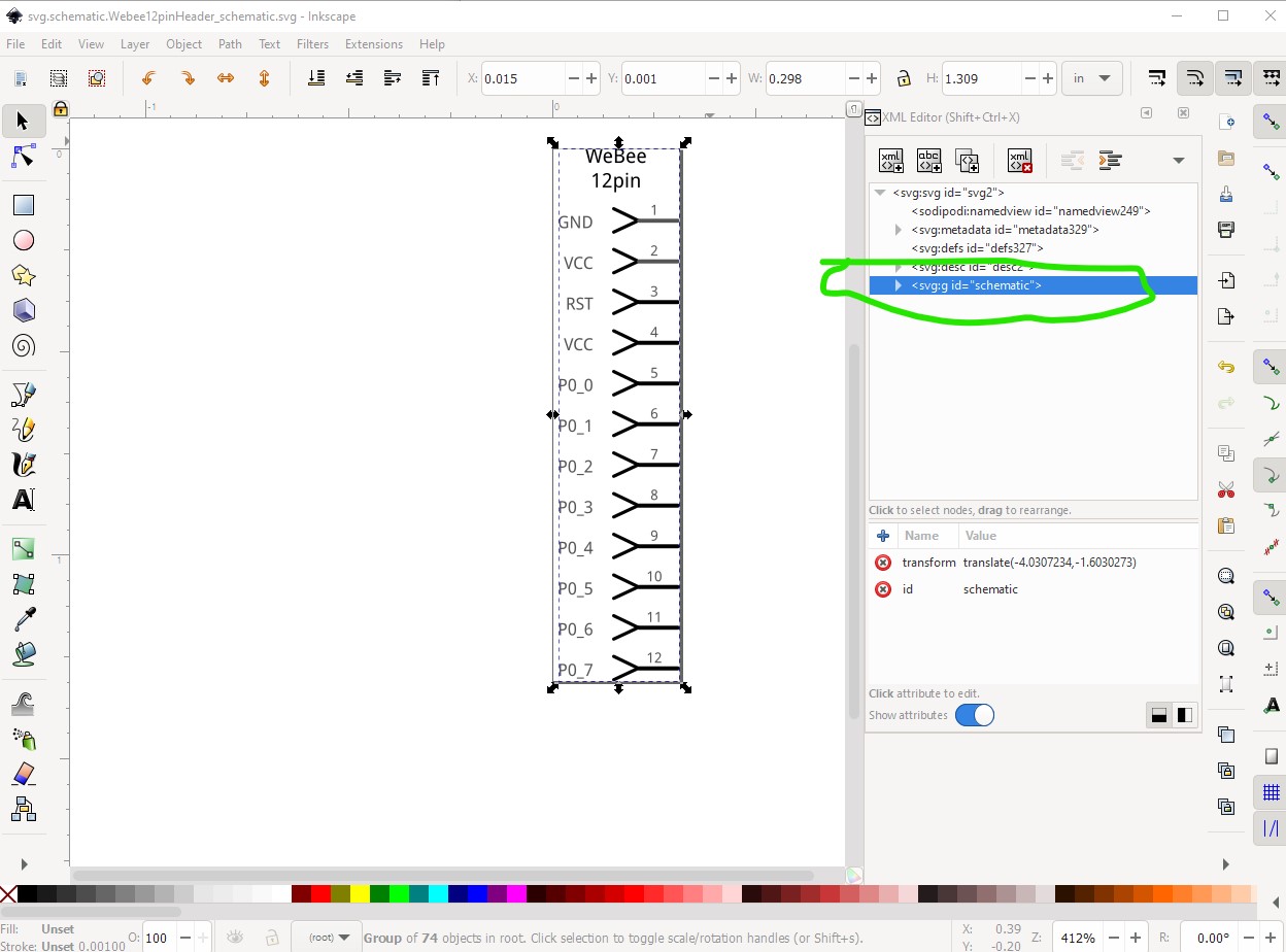
This is a later (so far unreleased) version of FritzingCheckPart so you won’t see some of the error messages. The missing layerId is because the enclosing group needs to have id breadboard.

like this

the name needs to match the layerId in the fzp file
<views>
  <iconView>
    <layers image="breadboard/Webee12pinHeader_breadboard.svg">
      <layer layerId="icon"/>
    </layers>
  </iconView>
  <breadboardView>
    <layers image="breadboard/Webee12pinHeader_breadboard.svg">
      <layer layerId="breadboard"/>
     </layers>
  </breadboardView>
  <schematicView>
    <layers image="schematic/Webee12pinHeader_schematic.svg">
     <layer layerId="schematic"/>
   </layers>
 </schematicView>
 <pcbView>
   <layers image="pcb/Webee12pinHeader_pcb.svg">
     <layer layerId="copper0"/>
     <layer layerId="copper1"/>
     <layer layerId="silkscreen"/>
   </layers>
 </pcbView>
which is the only error it found. It however missed one in pcb, all the copper needs to be in two nested groups called copper1 and copper0 like this
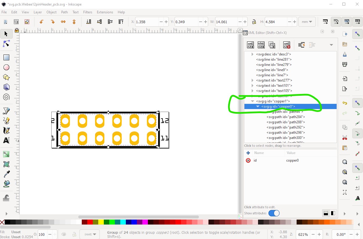
then all the lines and text need to be in a group called silkscreen like this
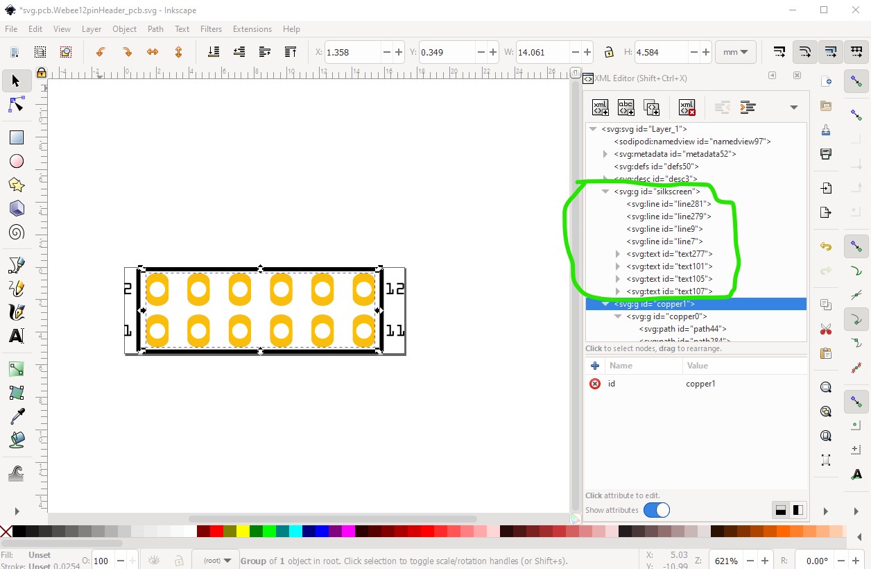
with that change (and the layerId in schematic the part should be correct.
and now check part runs clean
$ FritzingCheckPartw.py part.Webee12pinHeader.fzp
**** Starting to process file Startup, no file yet
**** Starting to process file part.Webee12pinHeader.fzp
**** Starting to process file svg.breadboard.Webee12pinHeader_breadboard.svg.bak
**** Starting to process file svg.schematic.Webee12pinHeader_schematic.svg.bak
**** Starting to process file svg.pcb.Webee12pinHeader_pcb.svg.bak
File
‘part.Webee12pinHeader.fzp.bak’
This is a through hole part as both copper0 and copper1 views are present.
If you wanted a smd part remove the copper0 definition from line 44
Warning 28: File
‘part.Webee12pinHeader.fzp.bak’
At line 96
name VCC present more than once (and should be unique)
In most cases duplicate names are not a problem. I’ll note in passing that the two vcc pins are bused (which means they connect internally) here that is correct as it is on the original part. By left mouse clicking on a pin all connections to that pin are displayed.
If you didn’t want them bused you need to modify the bus definition in the .fzp file here:
<buses>
  <bus id="VCC">
    <nodeMember connectorId="connector1"/>
    <nodeMember connectorId="connector3"/>
  </bus>
</buses>
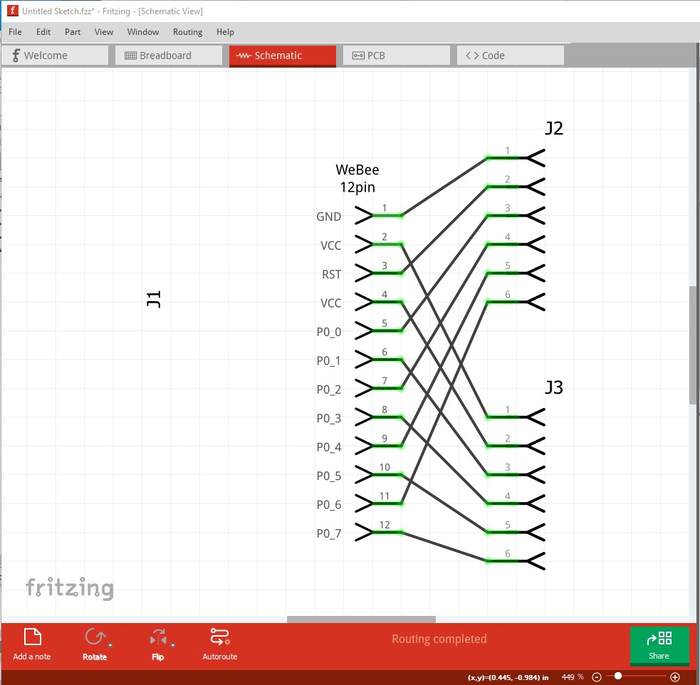
schematic is a little messy because I didn’t use single connectors in breadboard,
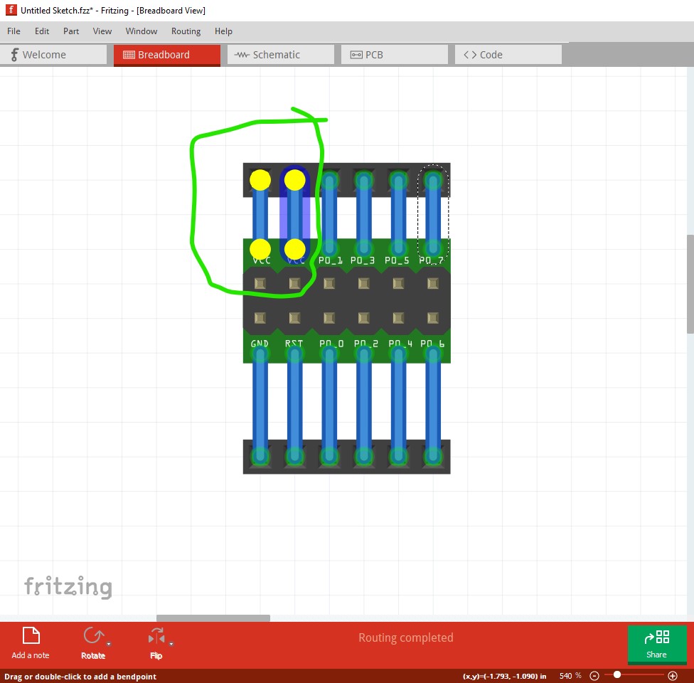
In pcb, if I set the grid size to 0.05in, I can run traces between the pins on the new part like this
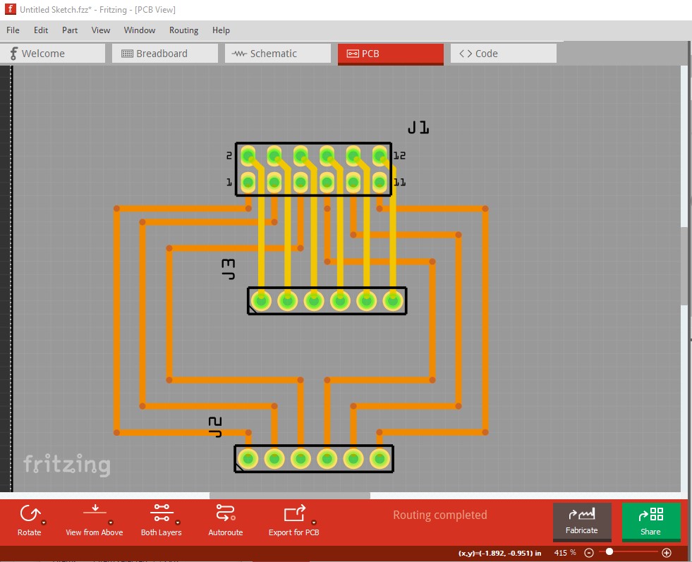
these were generated from this part
WeBee12pinHeader_2ndTry.fzpz (7.7 KB)
Peter
1 Like
Thanks @microMerlin,
Seems there is still a lot for me to learn about component creation - didn’t spot in the basis files the elements that are missing in my package. Have to go back and study the svg files from the basis in more detail.
Also thanks for the ideas about identifying the wrong character.
OH - thanks @vanepp
That’s a fantastic, but also a bit overwhelming portion of info. As I just concluded in previous mail, I still have a lot to learn. I will take your message and slowly work my way through it. I am sure it will give a lot - maybe also to others in the same situation thinking that it must be easy to take ‘a big component’ and cut away elements to get to a ‘smaller component’ that is basically a sub-set.
Take care.
Probably I have an Inkscape understanding issue and/or Frtizing terminology issue. When opening e.g. “svg.pcb.RPiHeader26p_1_pcb.svg” in the newly created (by @vanepp) component, the layers list is empty - it appears that there are no ‘layers’.
Instead, there are two groups of components. Sensible names, but when I ungroup to do my editing, that info from the group-names disappear. So, when @microMerlin mentioned that layers are missing, it seems it is rather groups with proper names that are missing.
I’ll continue my studies.
Correct. I was sloppy in my wording. What is missing is the Fritzing “layerid” which is implemented as the id of an svg (and Inkscape) group.
1 Like