can someone help me to find this module for fritzing? please 
1 Like
There is no such module just normal " LDR" .BUT IF YOU KNOW THE PCB YOU CAN MAKE THIS IN" FRITZING" AND USE IT OR USING INKSCAPE .
1 Like
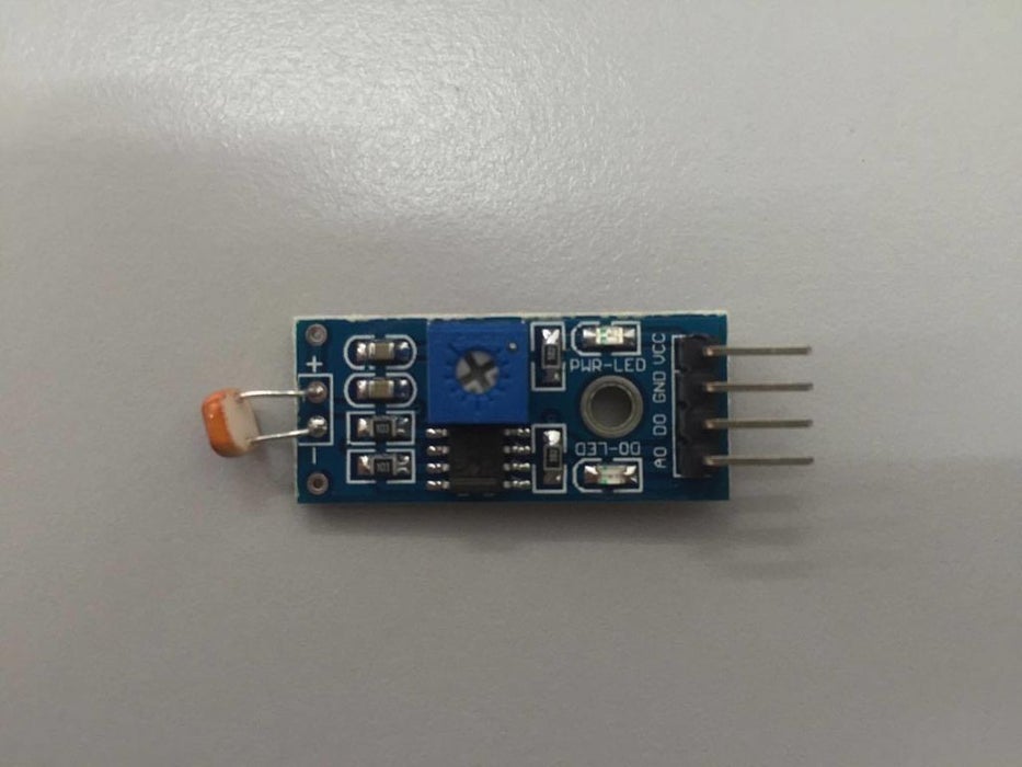
Welcome aboard! A google search for “fritzing part fritzing part ldr module” in the images section indicates this is a keyes KY-018 module and a search for “fritzing part KY-018” turns up
which may do you.
Peter
1 Like
Thank you sir, youre very helpfull… I forgot to keyes bundling froduct… Thanks again…
Your part has a number of problems:
$ FritzingCheckPartw.py part.CK-07_aec927b6e775740244da0b1d1ca98dc8_5.fzp
**** Starting to process file Startup, no file yet
**** Starting to process file part.CK-07_aec927b6e775740244da0b1d1ca98dc8_5.fzp
**** Starting to process file svg.breadboard.CK-07_18dbd62cba412dbc7bd36772c10be727_27_breadboard.svg.bak
**** Starting to process file svg.schematic.CK-07_18dbd62cba412dbc7bd36772c10be727_27_schematic.svg.bak
**** Starting to process file svg.pcb.CK-07_18dbd62cba412dbc7bd36772c10be727_27_pcb.svg.bak
File
‘part.CK-07_aec927b6e775740244da0b1d1ca98dc8_5.fzp.bak’
This is a through hole part as both copper0 and copper1 views are present.
If you wanted a smd part remove the copper0 definition from line 63
Modified 4: File
‘svg.breadboard.CK-07_18dbd62cba412dbc7bd36772c10be727_27_breadboard.svg.bak’
At line 3
ReferenceFile
‘CK-07breadboard.svg’
doesn’t match input file
‘CK-07_18dbd62cba412dbc7bd36772c10be727_27_breadboard.svg’
Corrected
Modified 4: File
‘svg.schematic.CK-07_18dbd62cba412dbc7bd36772c10be727_27_schematic.svg.bak’
At line 3
ReferenceFile
‘CK-07schematic.svg’
doesn’t match input file
‘CK-07_18dbd62cba412dbc7bd36772c10be727_27_schematic.svg’
Corrected
Modified 4: File
‘svg.pcb.CK-07_18dbd62cba412dbc7bd36772c10be727_27_pcb.svg.bak’
At line 3
ReferenceFile
‘CK-07pcb.svg’
doesn’t match input file
‘CK-07_18dbd62cba412dbc7bd36772c10be727_27_pcb.svg’
Corrected
Modified 6: File
‘svg.pcb.CK-07_18dbd62cba412dbc7bd36772c10be727_27_pcb.svg.bak’
At line 21
Added inherited stroke-width value
Modified 6: File
‘svg.pcb.CK-07_18dbd62cba412dbc7bd36772c10be727_27_pcb.svg.bak’
At line 22
Added inherited stroke-width value
Warning 6: File
‘part.CK-07_aec927b6e775740244da0b1d1ca98dc8_5.fzp.bak’
At line 2
ReferenceFile name
‘fc-51_85d98481ce3be6f2e9b641181c0f798b_1.fzp’
Doesn’t match fzp filename
‘CK-07_aec927b6e775740244da0b1d1ca98dc8_5.fzp’
Warning 14: File
‘part.CK-07_aec927b6e775740244da0b1d1ca98dc8_5.fzp.bak’
At line 76
terminalId missing in schematicView (likely an error)
Warning 14: File
‘part.CK-07_aec927b6e775740244da0b1d1ca98dc8_5.fzp.bak’
At line 91
terminalId missing in schematicView (likely an error)
Warning 14: File
‘part.CK-07_aec927b6e775740244da0b1d1ca98dc8_5.fzp.bak’
At line 106
terminalId missing in schematicView (likely an error)
Warning 14: File
‘part.CK-07_aec927b6e775740244da0b1d1ca98dc8_5.fzp.bak’
At line 121
terminalId missing in schematicView (likely an error)
Warning 11: File
‘part.CK-07_aec927b6e775740244da0b1d1ca98dc8_5.fzp.bak’
At line 129
Type female is not male (it usually should be)
Warning 14: File
‘part.CK-07_aec927b6e775740244da0b1d1ca98dc8_5.fzp.bak’
At line 136
terminalId missing in schematicView (likely an error)
Warning 14: File
‘part.CK-07_aec927b6e775740244da0b1d1ca98dc8_5.fzp.bak’
At line 151
terminalId missing in schematicView (likely an error)
Warning 36: File
‘part.CK-07_aec927b6e775740244da0b1d1ca98dc8_5.fzp.bak’
Connector0 doesn’t exist. Connectors should start at 0
Warning 35: File
‘part.CK-07_aec927b6e775740244da0b1d1ca98dc8_5.fzp.bak’
Connector0 doesn’t exist when it must to stay in sequence
Warning 19: File
‘svg.breadboard.CK-07_18dbd62cba412dbc7bd36772c10be727_27_breadboard.svg.bak’
At line 1
Height 103.15 is defined in px
in or mm is a better option (px can cause scaling problems!)
Warning 19: File
‘svg.breadboard.CK-07_18dbd62cba412dbc7bd36772c10be727_27_breadboard.svg.bak’
At line 1
Width 39.69 is defined in px
in or mm is a better option (px can cause scaling problems!)
Warning 19: File
‘svg.schematic.CK-07_18dbd62cba412dbc7bd36772c10be727_27_schematic.svg.bak’
At line 1
Height 28.8 is defined in px
in or mm is a better option (px can cause scaling problems!)
Warning 19: File
‘svg.schematic.CK-07_18dbd62cba412dbc7bd36772c10be727_27_schematic.svg.bak’
At line 1
Width 64.35 is defined in px
in or mm is a better option (px can cause scaling problems!)
Warning 19: File
‘svg.pcb.CK-07_18dbd62cba412dbc7bd36772c10be727_27_pcb.svg.bak’
At line 1
Height 40.41 is defined in px
in or mm is a better option (px can cause scaling problems!)
Warning 19: File
‘svg.pcb.CK-07_18dbd62cba412dbc7bd36772c10be727_27_pcb.svg.bak’
At line 1
Width 91.43 is defined in px
in or mm is a better option (px can cause scaling problems!)
Error 69: File
‘svg.schematic.CK-07_18dbd62cba412dbc7bd36772c10be727_27_schematic.svg.bak’
At line 9
Found a drawing element before a layerId (or no layerId)
Error 74: File
‘svg.pcb.CK-07_18dbd62cba412dbc7bd36772c10be727_27_pcb.svg.bak’
At line 20
Connector connector4terminal has no radius no hole will be generated
They can all be fixed by the information in this tutorial
Randy’s Inkscape schematic extension (in the tutorial) is the best way to make correct schematics (assuming you use Inkscape.) You will likely need to rescale the svgs after changing the dimensions from px to inches (also detailed in the tutorial.)
Peter