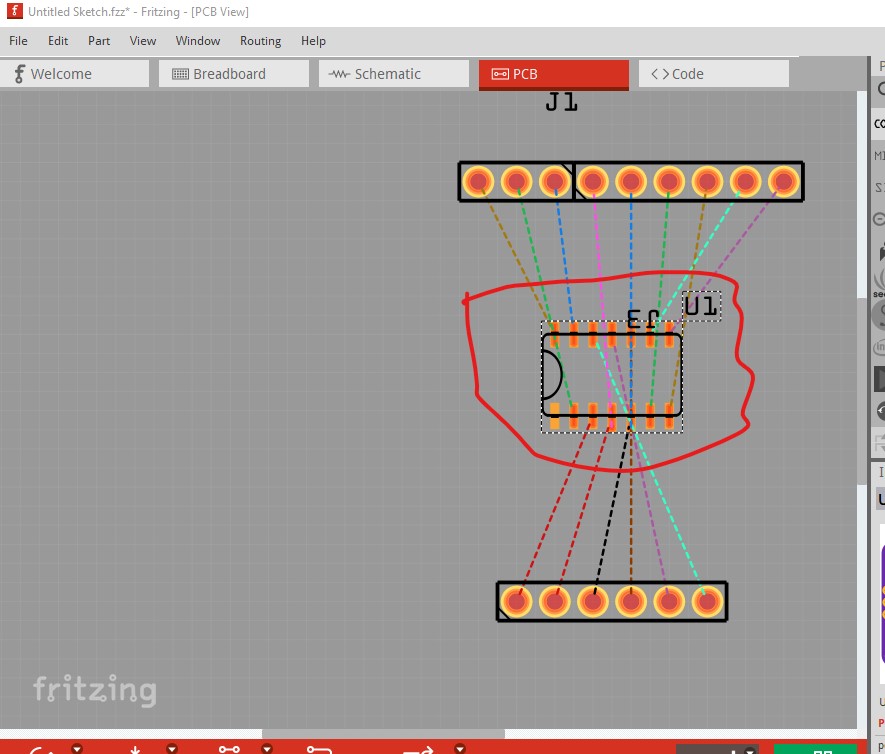
The PCB view is for the chip alone, not the additional circuitry on the module, but apart from the DC blocking capacitors it’s pretty much the same. I had to add overlapping PCB pads to account for the duplicate 3V3/GND pins on the module.
Your part has a number of problems. This tutorial may help with curing them:
The first thing I did was run FritzingCheckPart.py against the part to check its integrity. Here is an edit for size summary of its output (it is very verbose.!)
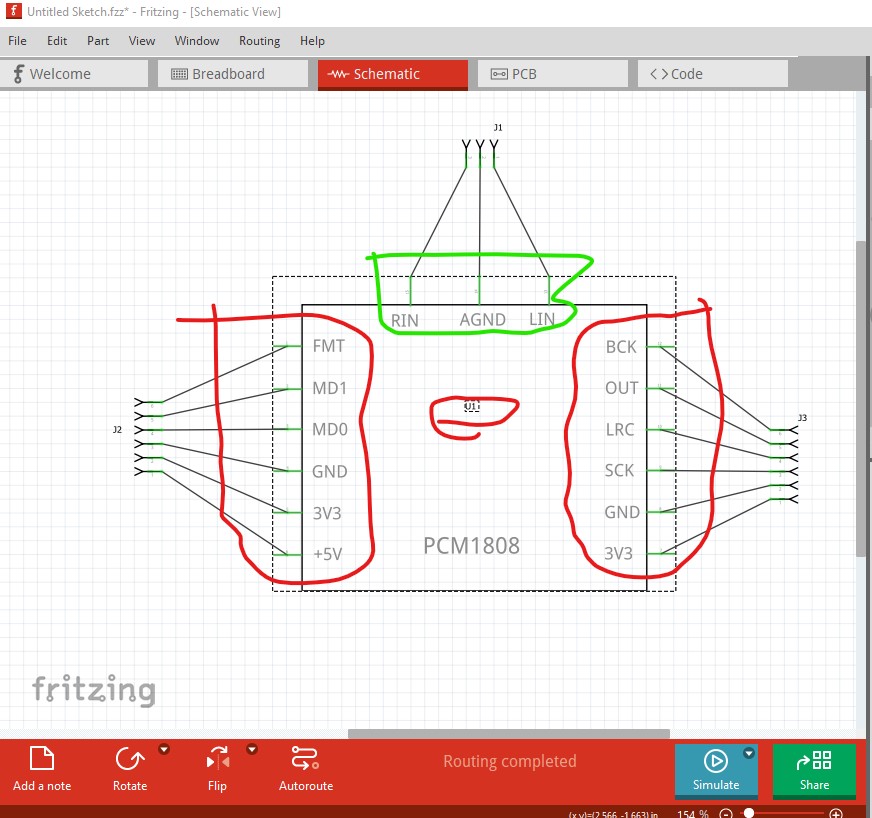
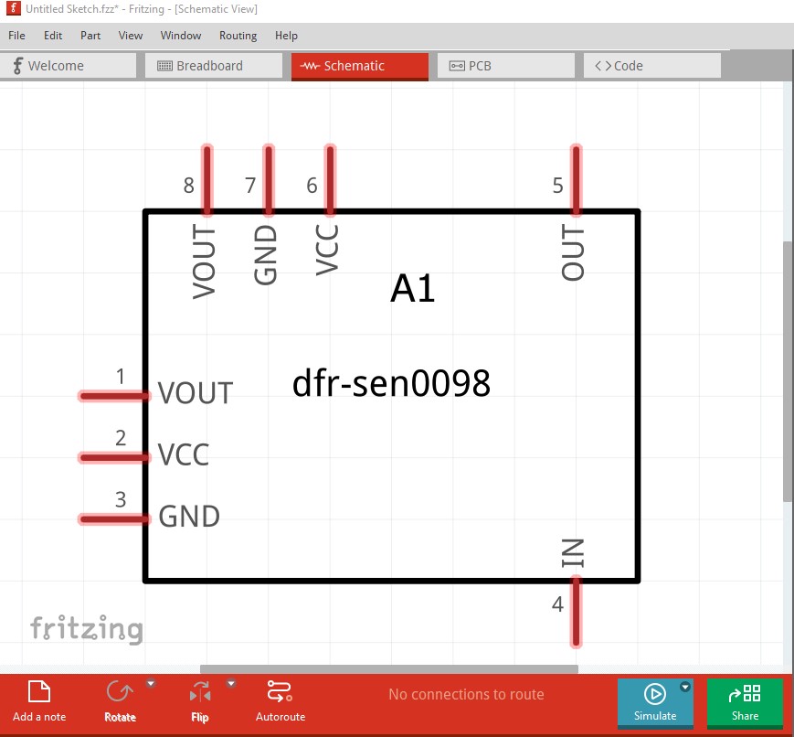
schematic less so. Here we see the problem with no terminalIds, instead of connection to the end of the pin (as the first three pins do) they connect to the center of the pin. Fritzing is supposed to correct this but doesn’t (as in this case) always do so. As well the label on the part is wrong. It is U which indicates an IC, it should be A (for assembly) instead. As well the part is too large, it is preferable to use Randy’ Inkscape extension (detailed in the tutorial) to make schematics as they then meet the graphics standard documents.
edit: replace the wrong image with the correct one …
Thanks a lot for the feedback. I understand your point about the missing terminals in the schematic view (although I think you pasted a duplicate of the PCB view in your message).
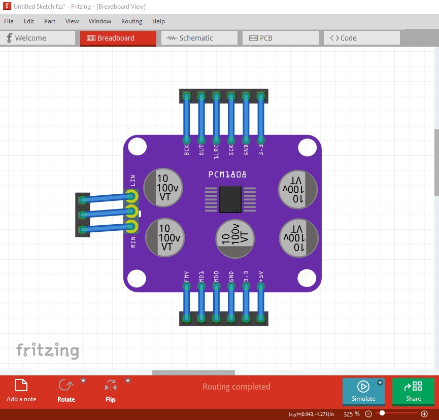
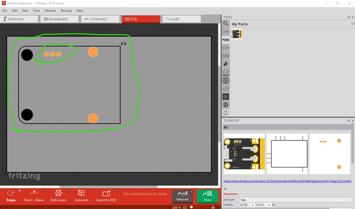
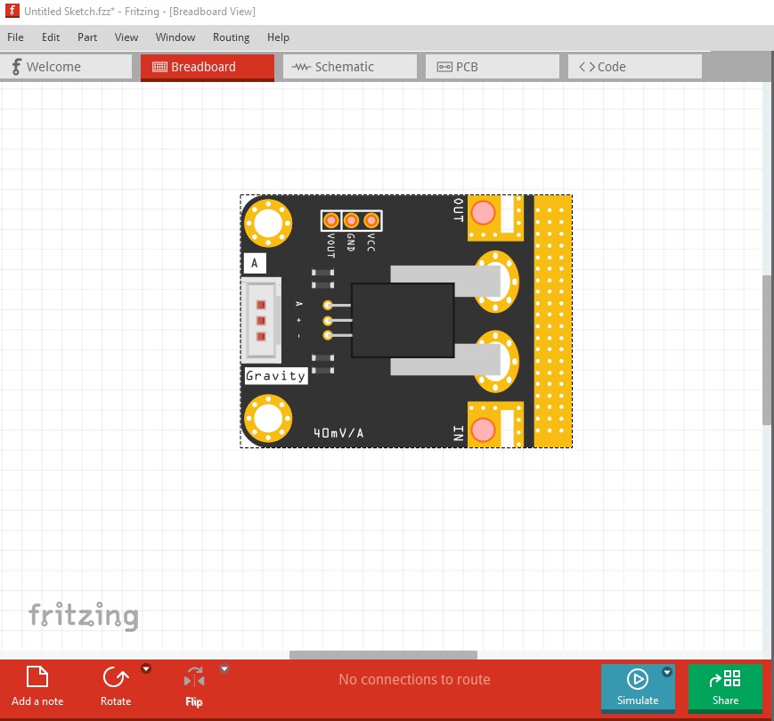
About the PCB view: I opted to provide for a bare PCM1808 chip rather than a PCB profile for the breadboard module. In my application, I am developing on a breadboard using the module, but my end goal is a PCB that will accept the SMD chip. The module connections all correspond to pins on the chip, and only one pin of the chip is not available on the module. However, the module incorporates some additional circuitry (the visible electrolytic and some smaller discretes). I haven’t seen a schematic for the module, although I can guess that two of the electrolytics are providing DC blocking for the analog inputs.
Anyway, I very much appreciate your mentoring, and I have a much deeper understanding of the structure expected in the SVGs associated with Fritzing parts now.
Is there a DIP version of that chip? It would probably be better to use that for breadboard (or a dip carrier) instead of the module, so that any ‘support’ electronics that the pcb needs will show up in the other views.