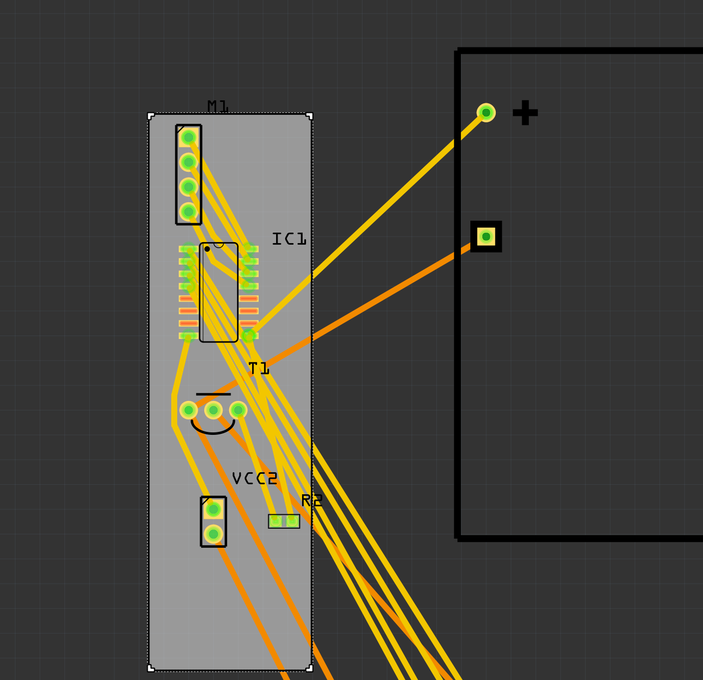
The black box outline on the right side is my VCC1 9V supply terminals), the bottom two in the grey area is my VCC2 (4.8V supply terminals), are the dots shown there places where i can solder the wires for my power supply?
The top left corner is my motor terminals (vertical 4 dots), the stepper motor they had only comes with 4 terminals i need a one with 5. Can i add a extra dot to solder the wires from the motor?
For the IC1 do they add the IC to the board or holes are added to solder the IC ourselves?
How do i make my PCB more neater i tried the auto route function but it keeps giving me the same layout.
Any help is appreciated and thank you so much to you guys in advance.
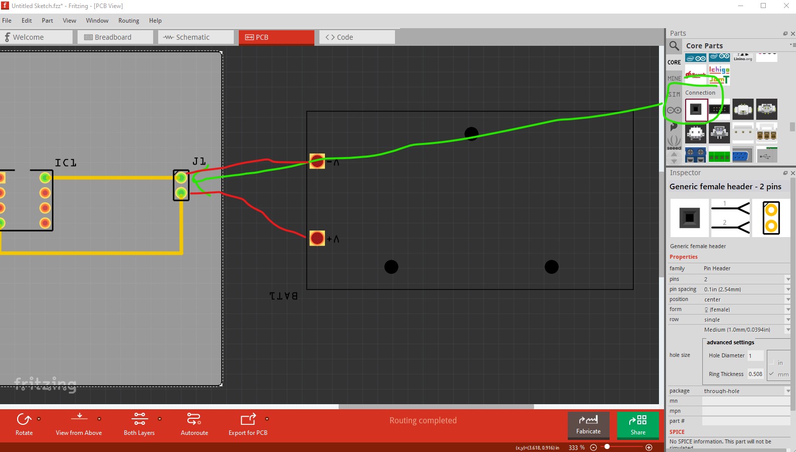
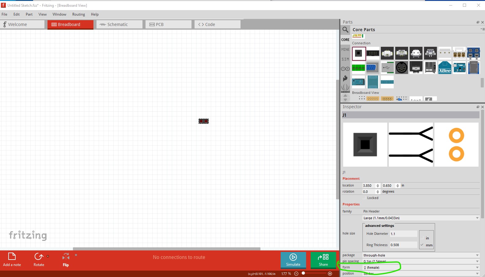
No. The pads need to be inside the grey pcb area. Everything outside that area will be truncated and not appear on the board. To put pads on the board the easiest way is likely to put a 2 pin header (which will produce a pad to solder a wire to) on the edge of the board like this:
the red line are wires from the board to the power supply.
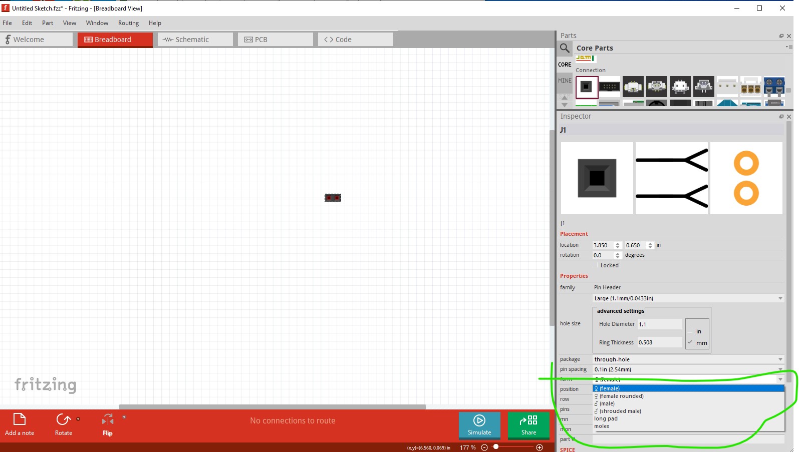
The same thing applies here, if you change the number of pins from 2 to 5 you will get a 5 pin connector. The rub is that unless you change the motor part you will have to manually route the motor connections to the new connector. A better bet would likely to be to use the 5 pin stepper motor (found by a google search of the form “fritzing part 5 wire stepper motor” which in general is a good way to find parts.
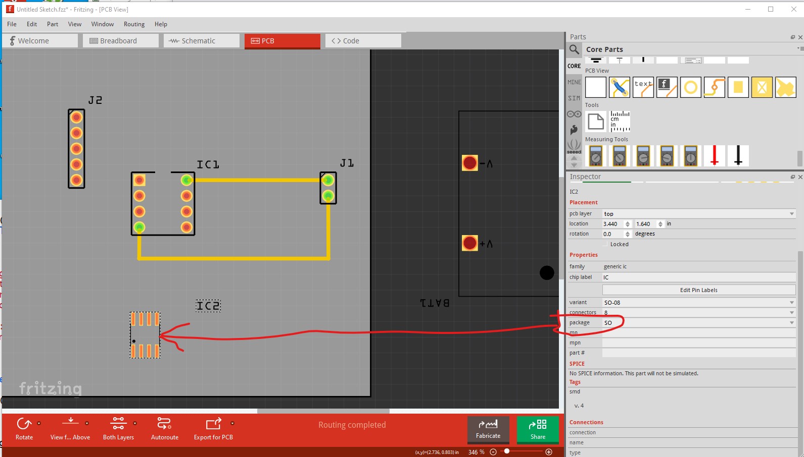
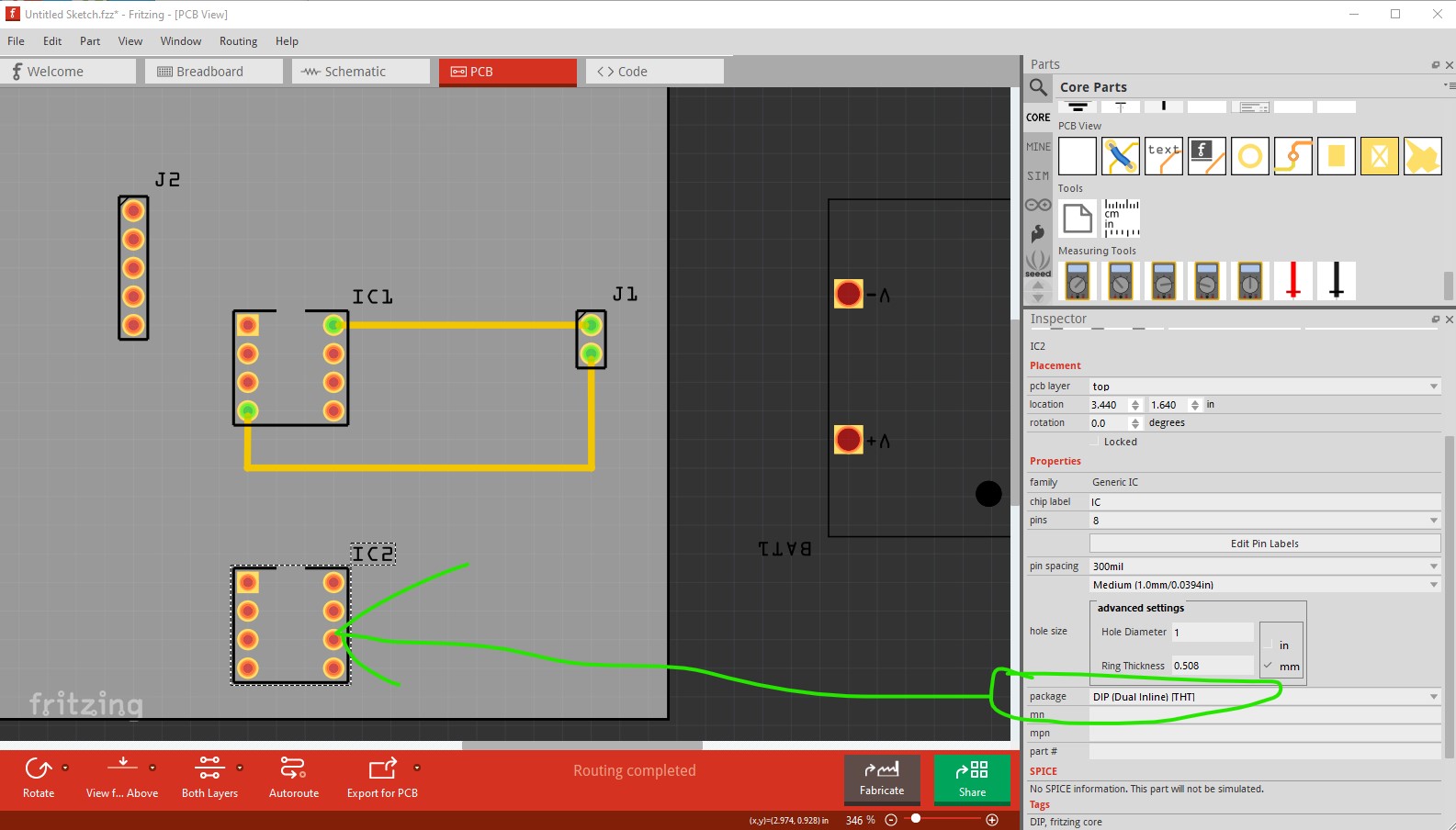
The IC you have selected (modifiable in Inspector like the header) is SMD so it has no holes as it solders to the top of the board. If you wanted holes you need to select a THT part like this:
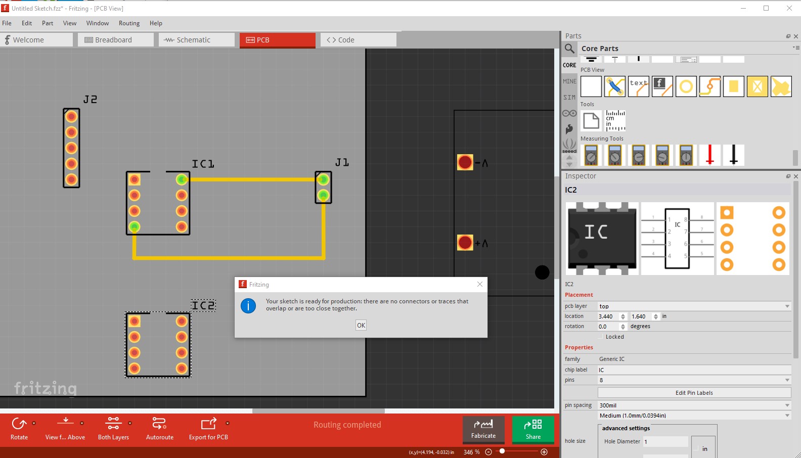
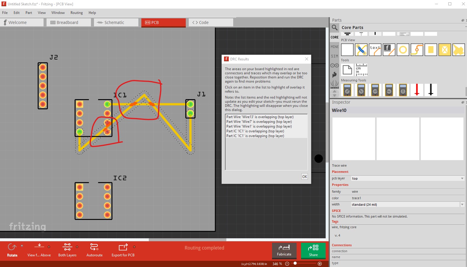
In general autorouting is convenient but almost always a poor choice. As well you need to run DRC (which will almost certainly fail on your board) like this:
where it has flagged the various errors with red marks. To correct you layout you manually need to click on the traces and move them to the appropriate place. It can help to set the grid size smaller via View->set grid size as well although for a simple board the standard 0.1in grid is fine.
Hope this helps and feel free to ask further if it doesn’t.
So the circle thingy denotes that a part is insertable on there instead of it being soldered on there permanently by the manufacturer, also thank you for the link you provided i am working with the exact same motor and the driver.
Typically they are both soldered on to the board, the circles indicate that a hole will be drilled to insert a through hole part like a typical DIP IC or a resistor whereas a pad indicates an SMD (surface mount device) part that solders to the top or bottom of the board. Most parts are available either through hole or SMD these days so which you choose depends on which parts you have (or intend to buy.)