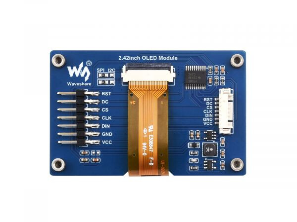
I am looking for a fritzing file for the Waveshare 2.42inch OLED Module in order to make a simple mounting pcb to interface with a ESP-32.
A similar fritzing file of this part exists here, however the dimensions and location of mounting/through holes are not the same as the Waveshare version.
This part should do what you want. Note pcb view has been suppressed as not useful.
edit:
add pcb as requested. I didn’t change the moduleId so to load the new part you will need to delete the current part from your mine part bin, then shut down Fritizing answering yes to save parts and save bins (you don’t need to save the sketch) to really delete the part before it will let you load the new one.
It won’t connect to a pcb. It has a connector on one end which goes to wires and a right angle header on the other which also won’t connect to a pcb. A standard 7 pin header will give you holes in the pcb to connect wires to though (which is why pcb is suppressed.)
I see, I was planning on desoldering the header and replacing it with a standard 7 pin one instead of a right angled header, and then soldering to a PCB…?
That chould work (the desoldering may damage the board of course) but then there isn’t enough information to place where the header should be in pcb. All that I have seen is images which are not of the highest quality. There don’t appear to be any layout documents which are sometimes available with dimension information.
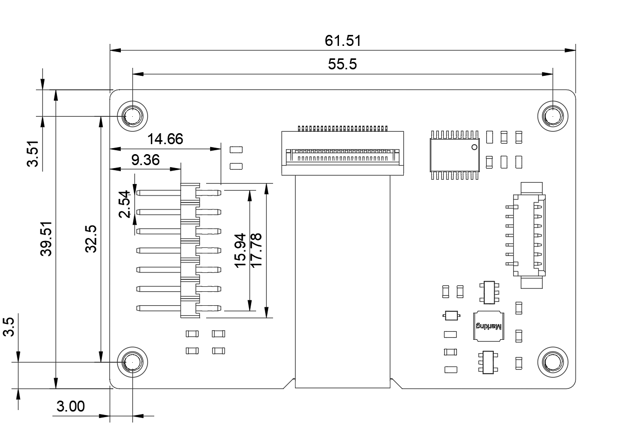
I would assume that the header would sit below the holes where the right angled header is soldered to currently, there is this pdf on the website although i’m not sure this contains enough information to determine the location of the holes in the board.
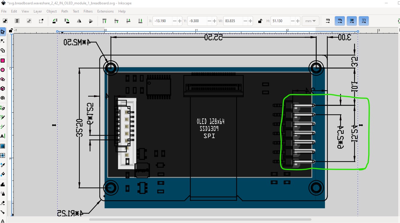
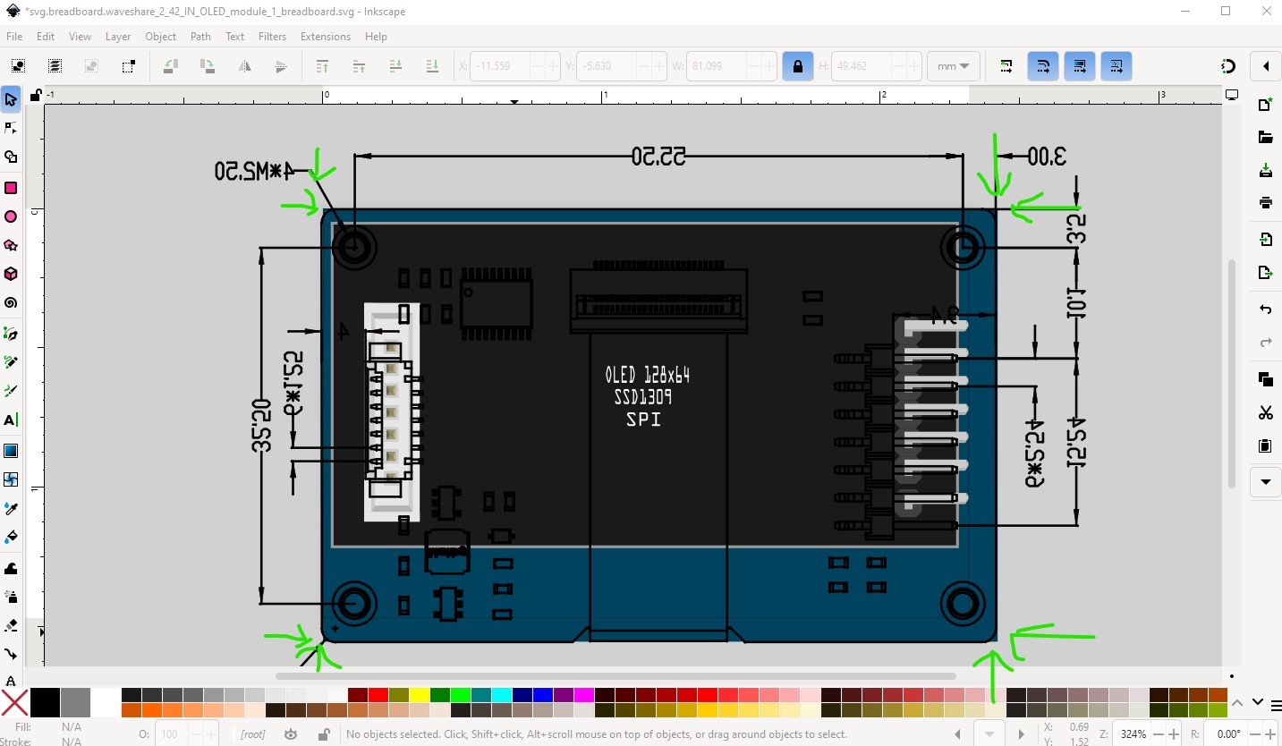
The pdf does not appear to be to scale (possibly to prevent exactly what I am doing.) I hadn’t gotten far enough down to see it and it provides dimensions I didn’t have, but adjusting the svg doesn’t match. Here I adjusted the rectangle to be 61.5mm by 39.5mm which is the outer dimensions of the board. I then scaled the pdf so that the header is exactly 0.1in as it is in real life (and is the only dimension I am sure is accurate.) That makes the rectangle too large if their measurements are correct.
makes the header (which is the only thing I know the size of) the incorrect size. This may be as noted to prevent reverse engineering of the layout. I expect the dxf file (which I think is autocad) would have the correct dimensions but I don’t have anything that will read dxf files. It is possible to make a pcb view o.1in header pads but it is unclear the positioning would be at all accurate (it may be close enough for what you want though as the header will fit, but the display may not be in the correct place when mounted though.)
I opened the dxf file and 3D model, and measured the dimensions based on that which seems to give the same dimensions as the pdf, as the header spacing is 2.54mm = 0.1in. Maybe the svg is incorrect? I will be working off the 3D model mainly in my design, so creating a pcb with 0.1in header pads would work, and I can adjust the pcb based off of the 3d model?
OK I just replaced the part with a new one that has pcb. Note the dimensions you posted are different than the one in the original pdf, so I used the new ones. You probably need to print out the pcb footprint at 1:1 scale (the default) and compare it to a real board to see if it works. The header will be correct, but the silkscreen and the holes may be misplaced depending on which dimensions are correct.