Degz – Power Distribution Board – Hi-Base – Hall Effect Sensor
Hello,
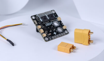
I am planning to connect 7 BLU 30A ESCs and 7 Mitras underwater thrusters using Hi-Base Power Distribution Board in a submersible.
I am planning to set up the system as follows:
Power will be supplied to Hi-Base Power Distribution Board from the power supply.
Power Distribution Board will provide power to both ESCs and Arduino Uno.
I am planning to use a voltage regulator before powering Arduino Uno.
Please help me it is very important for my project. I really need this piece, can you make it for me? to add to my electronic schematic in fritzing.
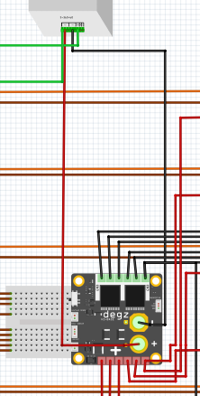
Hello, I am pulling + and - cables from the power supply to the power distribution board, but while the - cable works properly, the + power distribution board does not seem to detect it. What should I do?
power supply (+V) ----> power distribution board (BAT IN+)
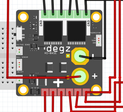
You need to connect them to a Frtizing part (other than the breadboard which you appear to have done. The green pads on the board are connected to something (without the sketch I can’t tell what) but the positive of the battery is not (as it is red still.) You would likely need a LIPO battery from core parts to connect to as the battery and other parts to connect to the control points which aren’t currently connected.
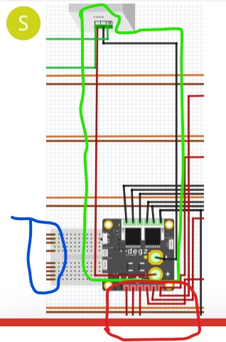
Specifically upload the sketch (the .fzz file.) Upload is 7th icon from the left in the reply menu. Images are basically useless when trying to diagnose problems, always upload the sketch that is breaking so we can download it and examine the real sketch to see what is wrong. As well right clicking on a connector will light all connections connected to that net which may tell you what is disconnected. The power supply is connected. Both ends of the connection look to be green indicating a connection (although without the sketch it is impossible to be sure.) The problem appears to be on bat+ which are red indicating no connection but the wires go who knows were as the sketch isn’t here. As well the wires in the breadboard (circled in blue) will the 4 on the top will all short together as will the 5 on the bottom. It is unclear (as we don’t know what they connect to) it that is intended. In schematic the power supply should show up as connecting to the Degz pins (but again without the sketch I can’t confirm that.)
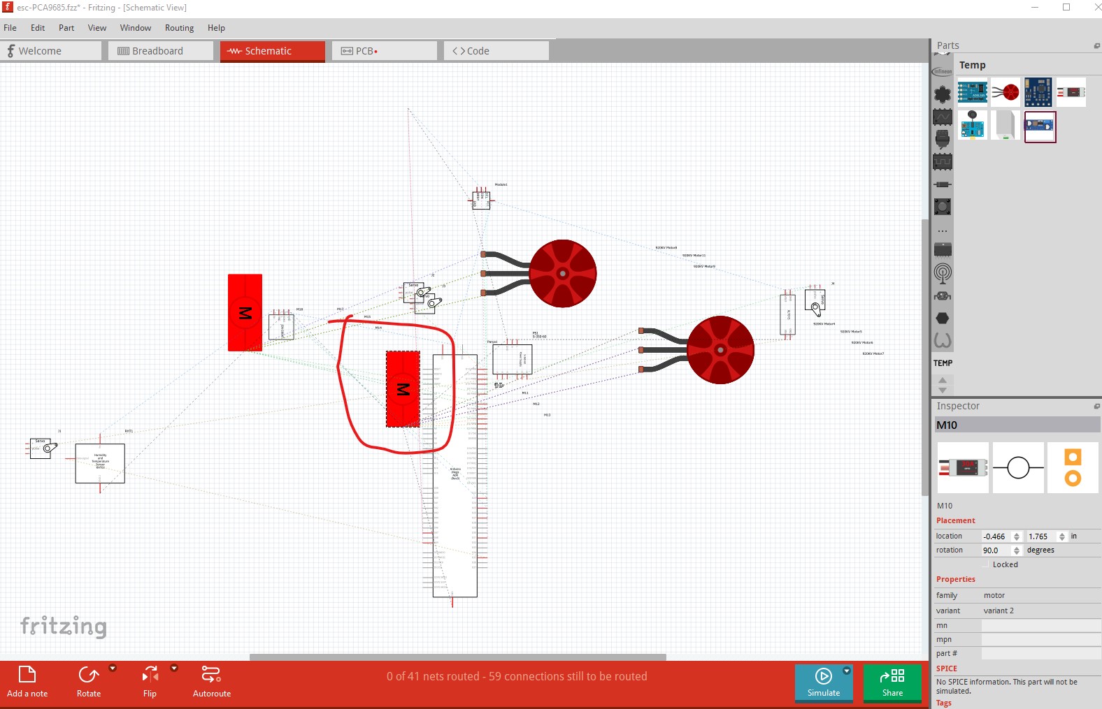
I can see why you are having problems. Some of your loaded parts are broken. For one the ESCs. Here in breadboard view it looks reasonable, it has 8 connections, but in schematic and pcb (in the lower left) it only has 2 connections each.
because there are undefined connections schematic can’t route. I can fix the part for you but I would need to know the web site for the ESC to get its connector data and physical size to fix the part. The part doesn’t have any url that would indicate what it is. As well when I move an ESC in breadboard the power and ground connections are not connected (I moved the part in the direction of the green arrow, the signal wires are connected and move with the part, the two power wires are not connected and don’t move.) I expect fixing the ESC will cure a lot of your problems and we can go from there if you can advise of a web site that has data on this ESC so I can figure out what to do with the part.
The latest problem is the Triple Axis Accelerometer Breakout - ADXL345.fzpz part has issues. Do you have a web site for the board you are using? The boards I see in a google search all have more than 4 pins and the part doesn’t have any indication of who makes it.
Actually I don’t know exactly either. I might have found it on the forum again. What do you recommend me for this?
I need acceleration and gyroscope sensors. My opinion is HW-579 seems good but I couldn’t find the manufacturer, there are only sellers. What can we do about this issue?
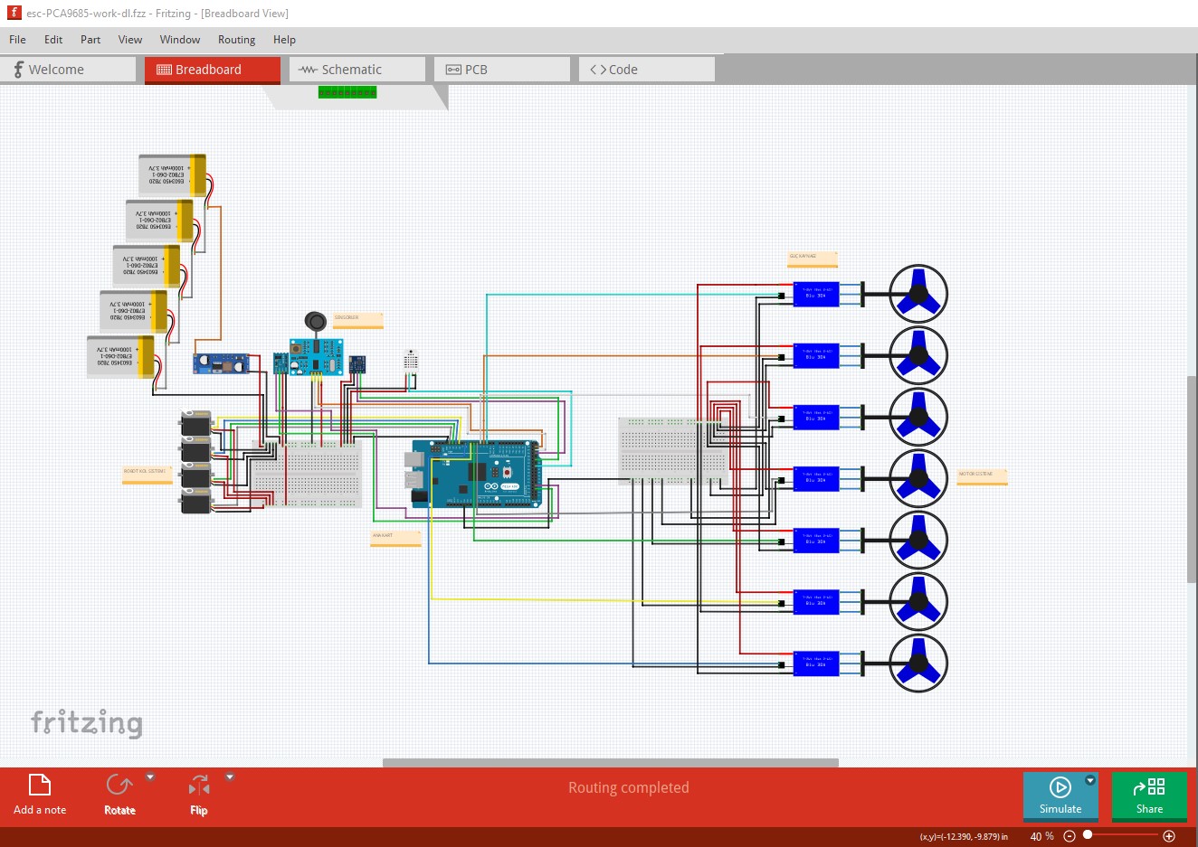
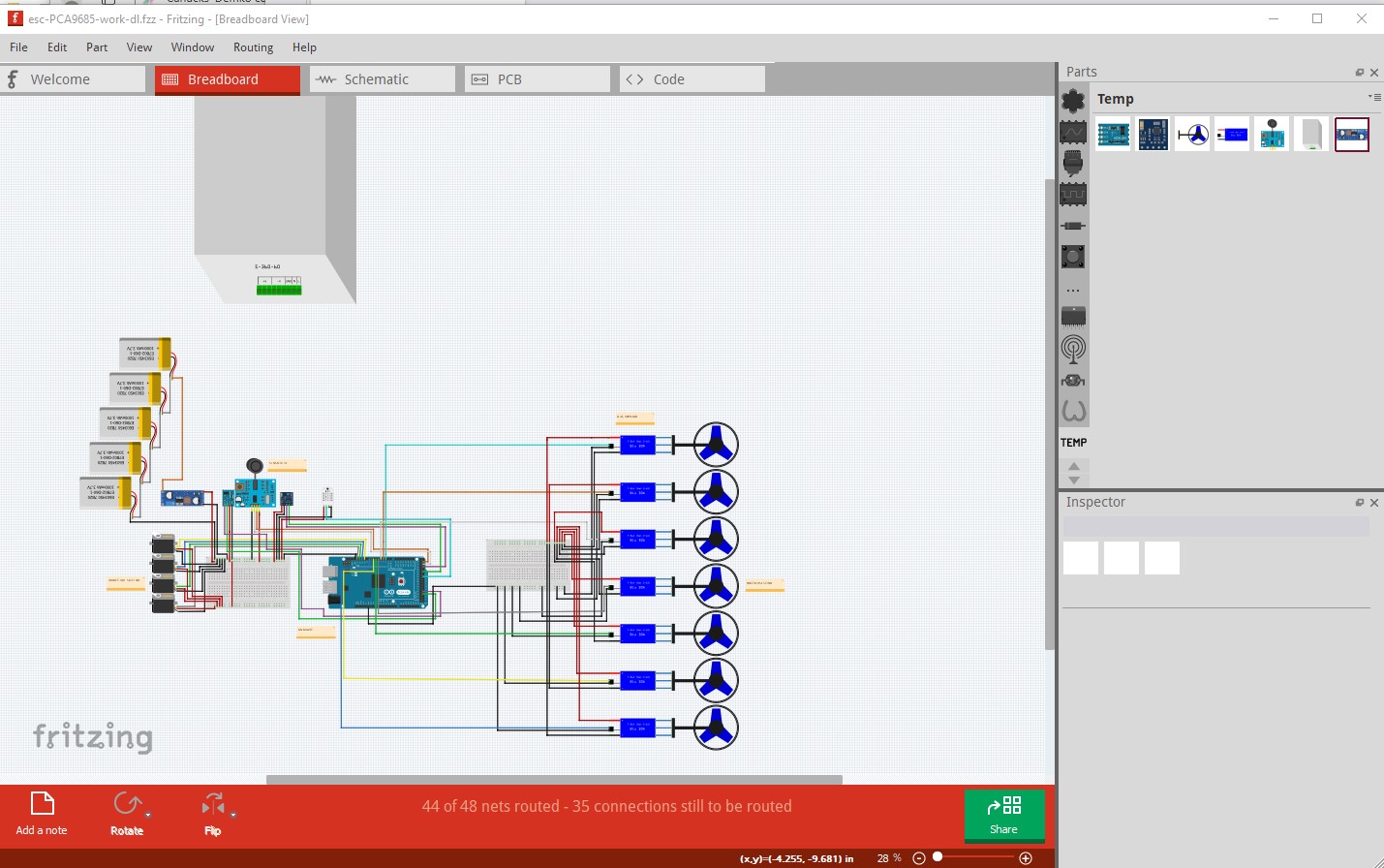
What I would do is pick a board that does what you need and I can make a part for it if there isn’t one. The ADXL345 has boards for Adafruit and Sparkfun (either of which may also have Fritzing parts for their board. I did see in the part for the ADXL345 that it may not be 5V compatible and would thus need a level translator to run on 5V. Here is the current version of your sketch with both ESC and the motor parts replaced, but the ADXL345 board doesn’t have anything in schematic and thus schemaitc doesn’t work. I also replaced the power supply with a battery (as that appears to be what the ESC is expecting) are you intending to power this device from the surface via a cable or run it on batteries?
I am using 0.9.4. but I think I need to update it. Can you replace the batteries with the power supply? and is there a need for a power distribution board in this system? Because I’m not sure if the motors will get enough power from the Arduino. So I was thinking of connecting the power supply to the power distribution board and giving all the energy from there to the motors and the Arduino.
I am using 0.9.4. but I think I need to update it. Can you replace the batteries with the power supply? and is there a need for a power distribution board in this system? Because I’m not sure if the motors will get enough power from the Arduino. So I was thinking of connecting the power supply to the power distribution board and giving all the energy from there to the motors and the Arduino.
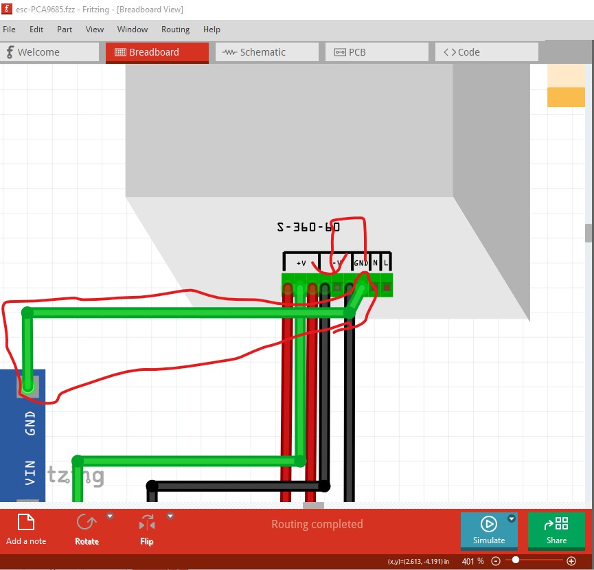
I keep most of the old versions around for testing. I can easily switch the power supply back in to the circuit. The arduino is unlikely to be capable of powering any motor (I would expect including the servos and certainly not the thruster motors.) The 24V power supply will be needed to power the thrustors and the XL7015 power supply module should supply 5V to the servos. I don’t know how much current it will supply off the top of my head, but I would expect a couple of amps. By the way in your original sketch this connection to power line ground is wrong. It needs to be on the power supply ground 2 pins over like this. The grnd on the power line side is the protective ground for the power line not circuit ground, that is only the 3 gnd terminals on the power supply.
As well the power (and especially the ground) for the thruster motors needs to be separate (and possibly not connected at all) to the digital ground. I expect the ESCs have the control signals opto isolated from the ESC, but it important to get the high current grounds isolated from the digital ground so you don’t run the risk of high current voltage drop causing ground level problems on the control circuit (that is why the ESCs are typically opto isolated.)