First, sorry I had assumed that the last link indicated you had found a working LED script and your problem was solved. That said, do you have a pointer to the web site or a data sheet (with a mechanical drawing with sizes and pin spacing) for the LED strip? The referenced strip has scaling issues (because it is dimensioned in px) and is pretty much unusable. With the needed dimensions and spacing something can probably be done but I need the size of the required part.
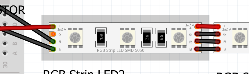
this is the size of LED strip. I think size is not much important because I can connect LED strip to PCB board by silicon wire, not direct soldering witch needs exact size. and there is lot of similar LED strip and its size may be vary from strip to strip.
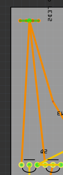
but real problem is the connector view of LED strip. as you can see in my picture in my post, The connectors are not seperated, they are clumped together in PCB view…
always thank you for your help. this part would help me lot much.
OK, here is a fixed part. PCB is set to be 4 pads set to take a 0.1in header which connects to both sides of the pins which are bused together internally. I assume you are aware you won’t be ab;e to drive these from a micro processor pin as they appear to draw around 1A on each color.