Since we did breadboard and pcb in part 1 here:
https://forum.fritzing.org/t/part-creation-howto-part-1-breadboard-and-pcb/7692
On to schematic
Again schematic as it stands is totally wrong, probably left over from the original part this was cloned from. So start from my schematic template and make a completely new one (the template has the advantage of being the right scale so it doesn’t need to be rescaled as the original schematic does.)
https://forum.fritzing.org/t/schematic-svg-template-howto/7583
svg.schematic.group-connectors-schematic-template_1_schematic.svg.fzp (37.5 KB)
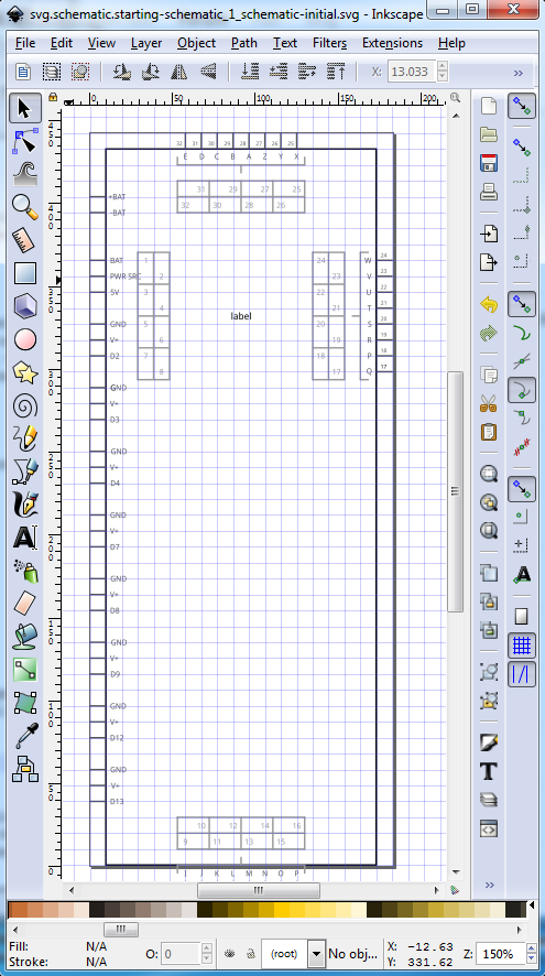
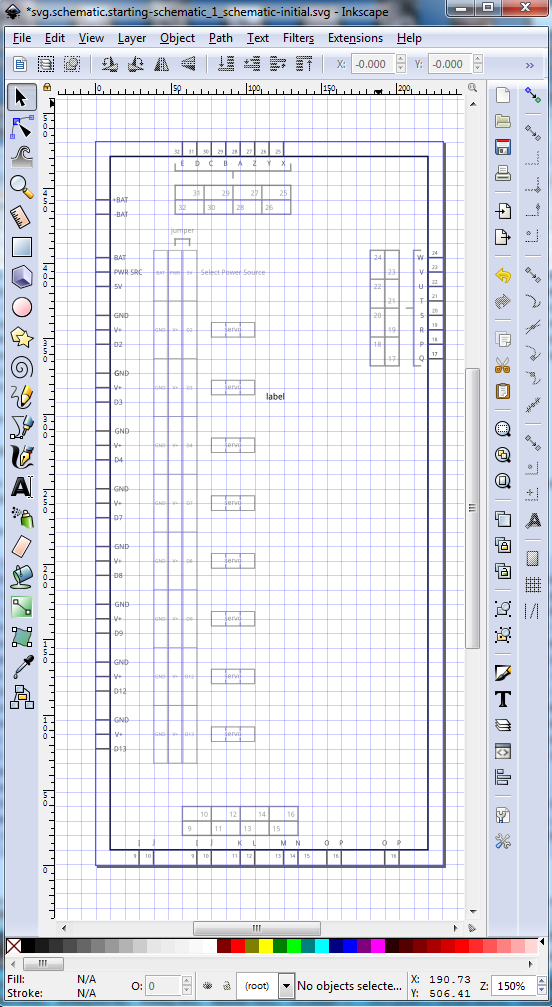
As before you need to remove the trailing fzp to convert this back in to a svg file. The forum often can not render svgs properly. Edit it in Inkscape then File->Save As->svg.schematic.starting-schematic_1_schematic-initial.svg to save a copy of the schematic svg leaving the template intact.
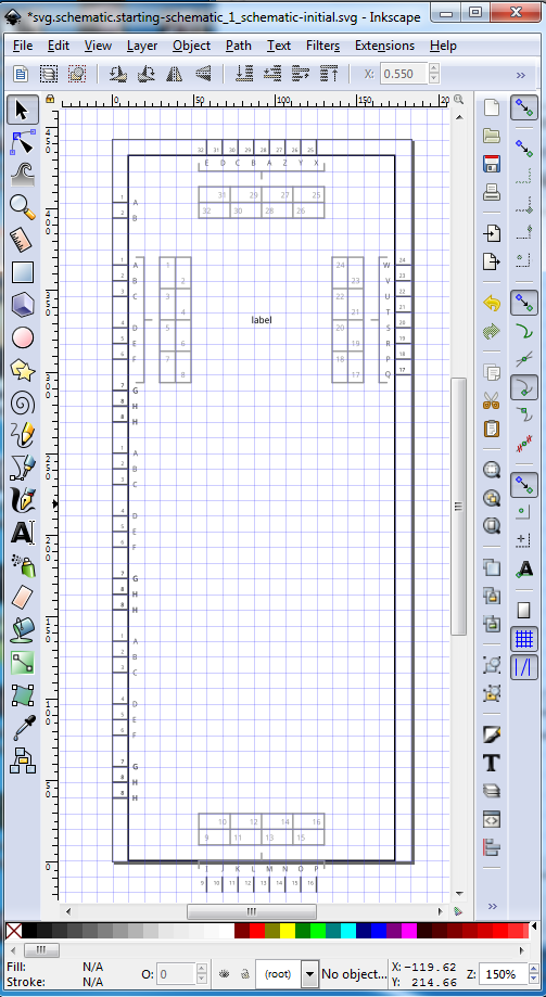
which should look like this:
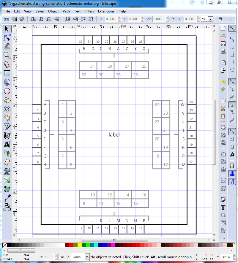
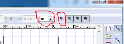
Now we need to figure out how to structure schematic. This particular part is a bit odd in that while it has 3 rows of 9/6 pin connectors on each side, the actual use of those connectors is 8/6 sets of 3 connectors for a servo running across the 3 connectors (the top of the 9 pin connectors are a power source jumper not a servo.) As a result I chose to break the 9 and 6 pin connetors in to groups of 3 (so the schematic of a standard servo will connect correctly to this board.) Unfortunately the pin out on our servos are in a different order than on this board so the wires will have to cross to connect, but that is life (actually it looks from a google search like the Fritzing parts are wrong, the standard servo pin out matches this board!). Thus we have 9 3pin connectors and 6 3 pin connectors for the two banks of servo connectors, 3 sets of 2 pin connectors (battery connection and the two motors), 2 sets of 3 pin connectors for the isp connection and 3 sets of 4 connectors 1 for the bluetooth connection, and two for the motor driver / data pin enable jumpers ( which allows use of the data pins without the motor driver by removing the jumpers.) Convention for schematic is inputs on the left and outputs on the right, so the two 2 pin motor connections should go on the right side, lets call the isp an input (it is actually both) and put it on the left, same with the 3 bluetooth connectors also on the left, that leaves us with the servo connections which are outputs and should go on the right. That however will make the schematic tall on the right with a large empty space on the left, not a good use of schematic space. So instead I chose to use an alternative layout (which I much prefer anyway) and make schematic match the breadboard view. I find this much more useful when debugging than the conventional schematic layour (and the usual EDA programs, where the schematic convention originates, do not have breadboard view.) Now to translate this in to a schematic. Start by setting the tool bar units to inches, and making sure scale stroke width is disabled like this:
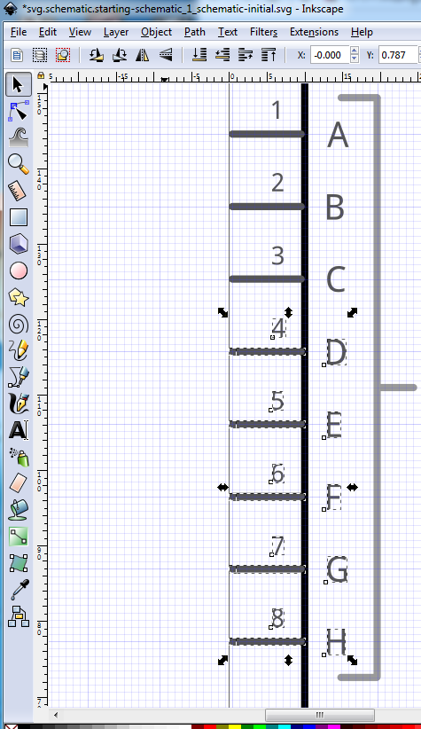
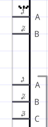
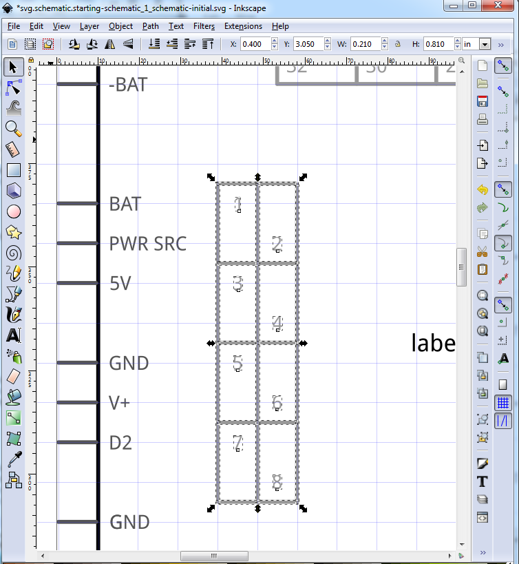
Applying the laziness principle, select pins 1 and 2 (being careful to avoid selecting the top line of the group structure):
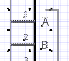
duplicate them (mouse right click_>duplicate) then move them up in y 4 positions to make the two battery terminals. This is lazy because pins 1 to 8 have correct connector numbers now and thus won’t need to be changed later unlike the two battery pins:
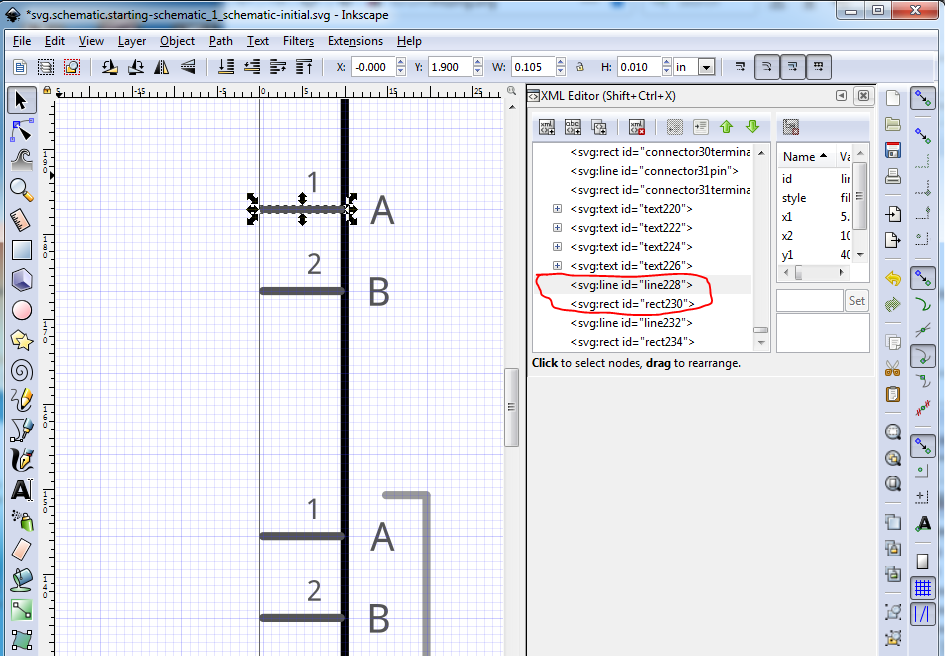
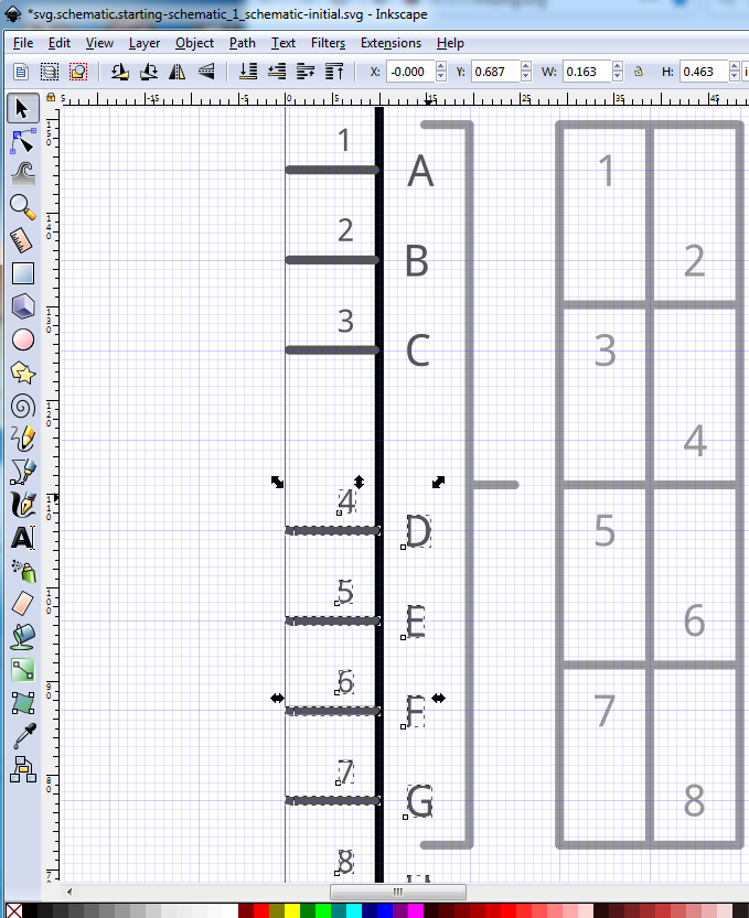
Of note here, is that the ids of the duplicated connectors have changed from connector0pin and connector0terminal to line228 and rect230 which will eventually need to change to connector27pin and connector27terminal to match the battery connector, but for now, this has left the original A and B connectors as connector0 and connector1 as they will eventually be. Now select pins 4-8 and move them down q position in y to leave pins 1-3 as the first servo connector:
then move them
Now duplicate pin8 and move it down in y 1 position to make 2 groups of three pins:
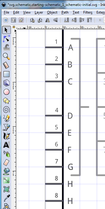
select the bottom 3 pins and move them down .1in in y:
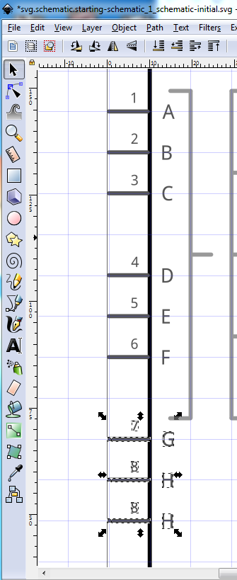
Now you have 3 of the needed 9 sets of servo pins. So select and duplicate all 3 sets them move them down in y til they is a .1 space between blocks, then do the duplicate again (to get up to 9 servo connections) and move them down again. you should end up with this:
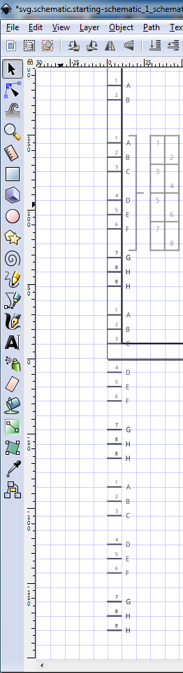
Now to clear visual distractions, select the rectangle and move it to below the last servo goup by a few grid bars, then increase the height of the rectangle til it is above the battery connector by a bit. Then select the 8 connectors that used to be on the bottom of the rectangle and move tehm down in y til they are again at the bottom of the rectangle where they should be and resize the drawing to adjust the view box creating this:
Now we will complete the left side of the drawing, the connectors are all in place, they just need relabeling and the addition of grouping information and connector numbers. First select and delete all the pin numbers (select carefully to not delete the terminalIds on the end of the pins though!) Wrong:
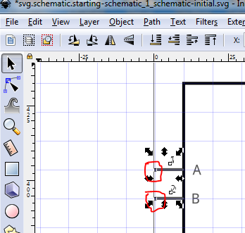
The red circles are the invisible rectangles that are the terminalIds which we need to remain present (because they are a pain to re add.)
![]()
While I’m here, use xml editor to set the connector name and the tool bar to verify the pin alignment. The pin number is obtained by clicking on the same pin in the breadboard svg like this:
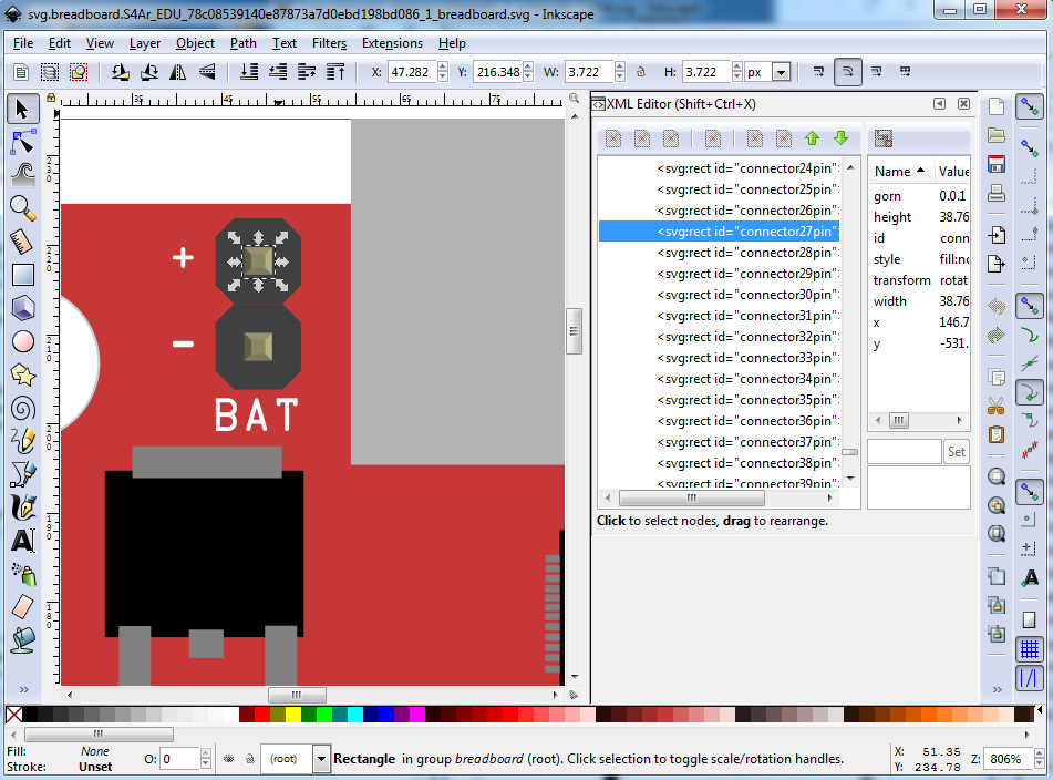
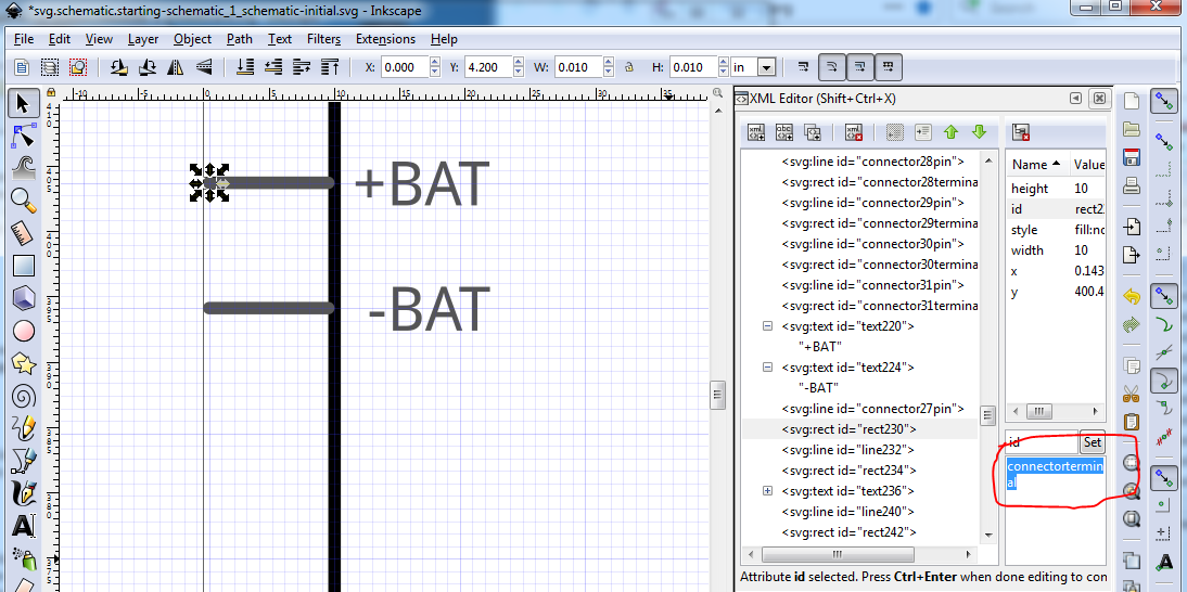
Note this is not as easy as it could be because it is almost impossible to select the pin by clicking on the pin in the image (there are too many constructs around the pin and it selects one of them instead of the pin rectangle, like this:
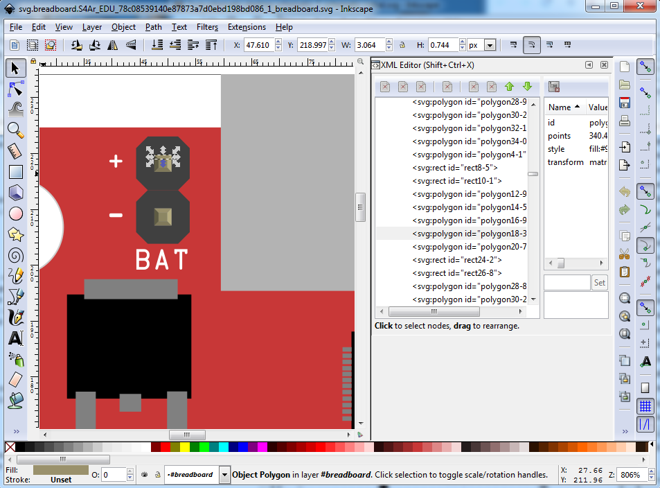
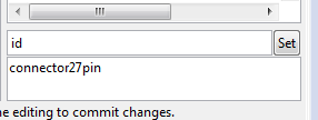
so I actually found the pin by stepping down the list of connectors until it highlighted (in this case I cheated by already knowing the pin number.) This is why having the pins in order at the bottom of xml editor is useful. That avoids having to search the entire document to find a pin. The laziest way I have found to set connector id is to copy “connectorterminal” to the clip board, then paste it in to xml editor like this:
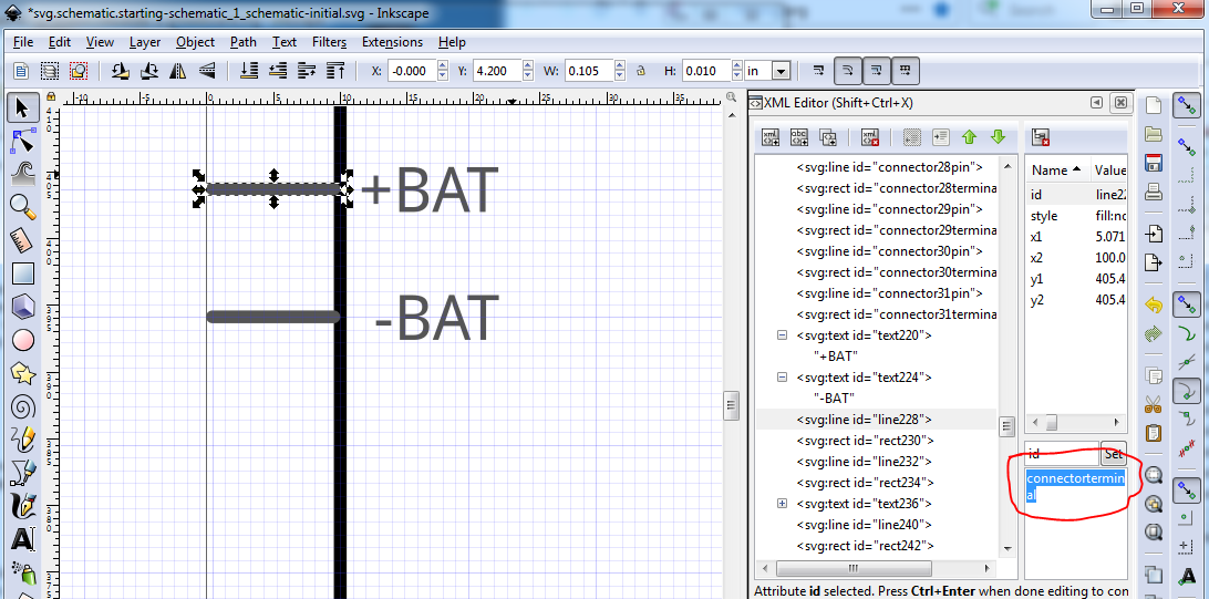
this is actually the pin side of the pair, so you need to select the terminal and replace it with 27pin (in this case) like this:
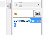
Then do the same to the terminal id:
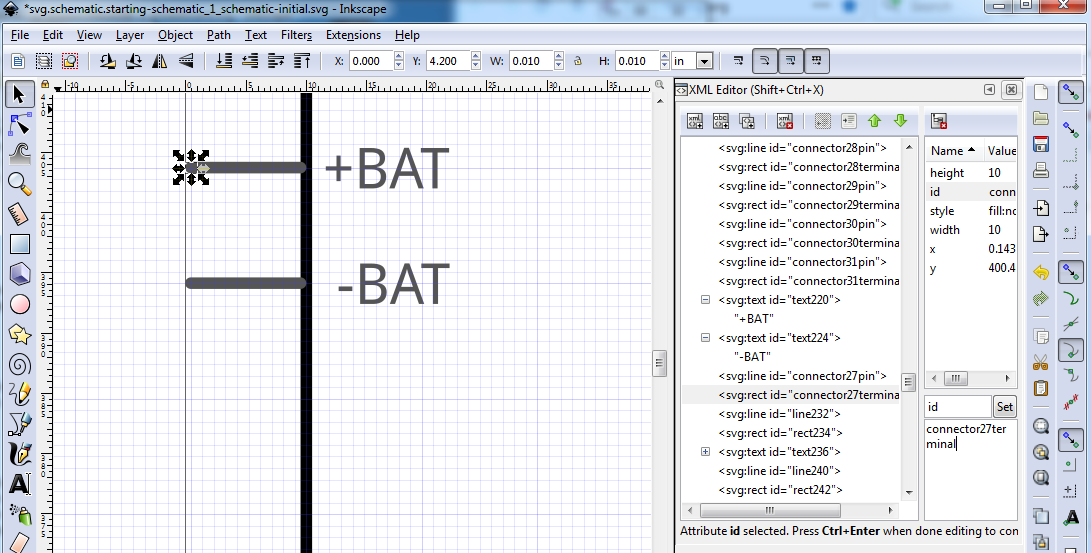
The idea is deleting the terminal and typing 27pin is less typing (and less prone to typos) than typing 27terminal to set the terminal id. Laziness at work. Now repeat this for all the other pins and set the pin labels. You should end up with an svg that looks like this:
svg.schematic.left-cons-done_1_schematic-initial.svg.fzp (44.8 KB)
Now we need to deal with the pin grouping stuff. Because of this part not being a standard dual row type connector but rather three vertical 9 pin connectors which actually connect 3 across horizontally, I chose to represent it that way. Thus the current dual row connector needs to move to the right in x to clear the PWR SRC text so do that first:
Now I need to create 3 vertical but seperate headers (rather than the current dual row) so reduce the stroke-width of the lines from 10 to 5:
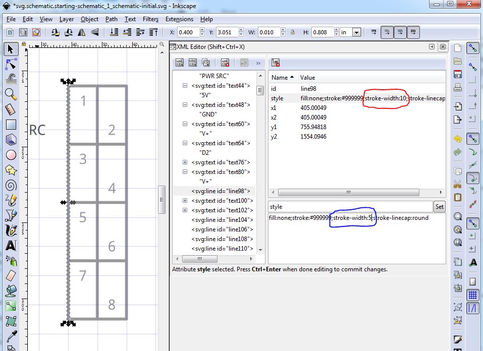
Then move the line down in y til it is below the last servo connector, then increase its height til it is just above the first servo connector. I prefer to put these lines centered on either the major grid line (true in x for this one) or centered on the 5th minor line (true in y in this case.) To do so you need to take the stroke-width in to account, so you need to add or subtract 1/2 the stroke-width ( 0.025in in this case) from the coordinate if you are setting the absolute position via the tool bar. I often find it easier to change dimensions to px, then move in px til the arrow on the bottom of the element aligns to the grid line like this:
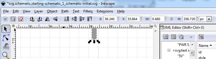
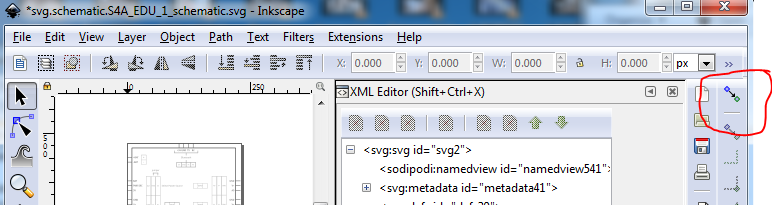
whichever way works best for you is fine. You can also click and drag the arrow on the element to move it up or down to align it. To do that you may need to turn snap to grid off like this:
on:
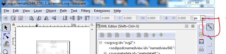
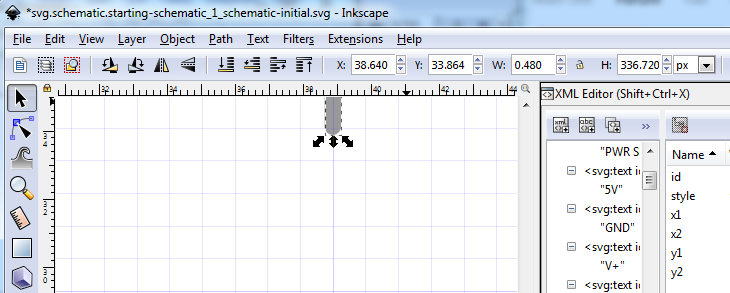
off:
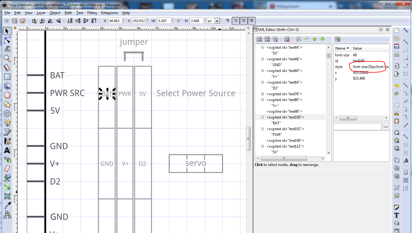
In this case because I want to make it clear there are three separate headers (rather than a dual row shrouded connector) I chose to set the x coord of the second vertical line to 0.4975in (the stroke width will increase that by 0.025in as noted centering the line on 0.495in.) The next line (the start of the next header) is at 0.5075in (which less half the stroke width leaves it 0.05 past the major grid line with 0.05in between the two lines. Now be lazy and duplicate the pair of middle lines and move it in x .1 in to form the header strip 2 / 3 boundary. Then duplicate the left most single line and move it right .2in to make the right side boundary of the 3rd header strip. More moving things around should give you this which is the start of the required layout (next you need to repeat all of this by duplicating and moving in x or y all the rest of the connectors.) Once it is doneit should look like this (note: I reduced the font-size from the default 49px to 35 px in the connectors):
svg.schematic.starting-schematic-left-done_1_schematic.svg.fzp (78.6 KB)
Now we move on to the bottom row. I’m cheating, because I already worked this out, and know that the bottom wants to look like this:
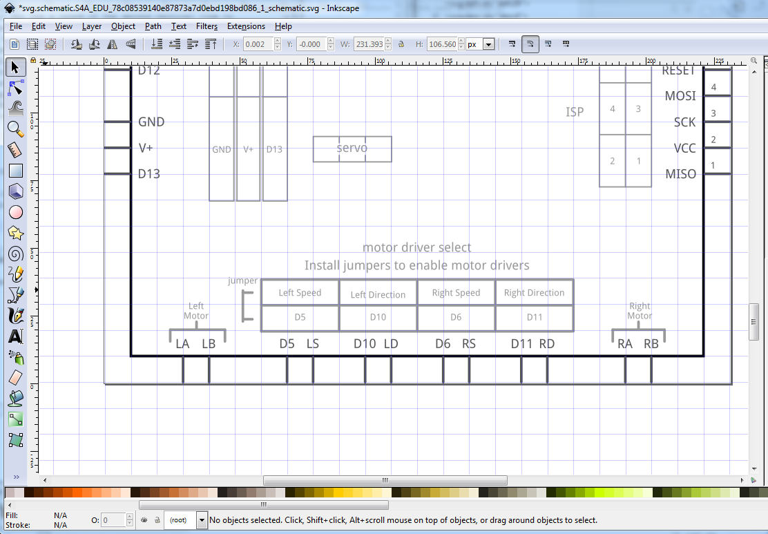
How I originally determined this is that across the bottom I needed 2 two pin motor connectors and a dual row 4 pin header pair that take vertical jumpers to connect the data lines to the motor driver input (without the jumpers the data lines can be used for purposes other than driving the motors.) So again the representation isn’t going to be the default dual row connector but rather two pins then a .1in space and two more pins. You need to work this out depending on the connections on the part you are making, this is how I chose to do this particular part. So given the starting svg above, we first need to move the entire bottom pin set down .2in in y, so select it all and do that, then move the rectangle down in y .2 in and increase its height by .2in to keep the top row correct. At this point a resize page is in order to remove the visual distraction of the viewbox being incorrect. Then duplicate the first two pins of the connector and move them left to become the two left motor driver pins. Then move the entire 8 pin connector right by .1in, move the dual row connector back 0.05in (via the tool bar x coord field, change 0.650 to 0.600.) Now select the last 6 pins and move them right 0.1in, repeat this for the last 4pins then the last 2 pins. Duplicate the last two pins and move them right by .4in to make the right hand motor connector. Now select the rectangle and increase its width by .5in to its final position. You now need to select the entire right hand connector at the top and move it right .5in, then again resize page to adjust the view box to the final configuration, leaving something that looks like this:
Now you need to set the connector pin and terminal ids from breadboard and adjust the connector box to match the final drawing above using the techniques as before to finish the bottom connectors. Then move on to the right side and top connectors until you have a schematic that looks like the final product:
svg.schematic.S4A_EDU_1_schematic.svg.fzp (106.7 KB)
save your final svg in to
svg.schematic.starting-schematic_1_schematic-initial.svg
for later because there are some intentional errors in
svg.schematic.S4A_EDU_1_schematic.svg
that we will use in part 3 of this series. Once you have completed that, schematic is done.
Later after you have run svg.schematic.S4A_EDU_1_schematic.svg
through FritzingCheckPart.py copy your
svg.schematic.starting-schematic_1_schematic-initial.svg
in to
svg.schematic.S4A_EDU_1_schematic.svg
and run it through FritzingCheckPart.py again to see if you did better on the typos than I did (instructions to do this are in part 4 of this howto)
We have now done all the svg files and now we move on the the fzp file (the xml file that ties all this together) in part 3 of this howto in:
https://forum.fritzing.org/t/part-creation-howto-part-3-fzp-file/7695