hello, I need this part for fritzing please help!
Welcome aboard! To my surprise we don’t appear to have one of these. A google search for “fritzing part nrf24l01 adapter module” doesn’t turn up anything appropriate. That may be because an Nrf24l01 will do in its place (the Nrf24101 is available in core parts.) To make a custom part we would need either a mechanical drawing of the board or at least a web site like this one with enough information to make one.
Peter
As you know nrf24l01 need a 10-47uf capacitor between gnd and vcc so I use it ,and ther is some capacitor and resistor but I don’t know connections .And I am afraid of I haven’t got enough time,it is for a competition can you send .fzp file?
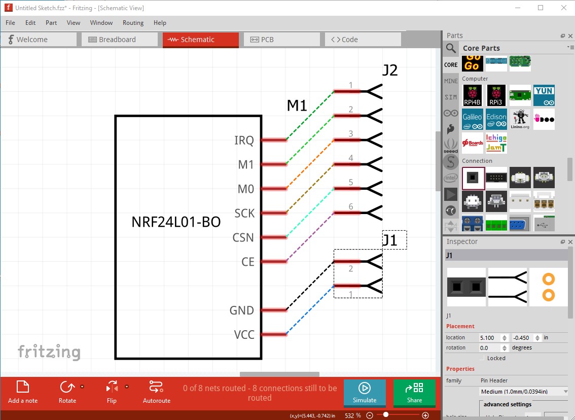
This should do what you want. It has a NRF24L01 attached to the connector but the interface is out the adapter board pins as in real life. There is no pcb view as it isn’t useful.
NRF24L01-BO.fzpz (11.2 KB)
Peter
Thanks for your part.I try make pcb color black(and add a sma socket),but in fritzing it is look green?
NRF24L01-BOv2.0.fzpz (76.4 KB)
pcb view isn’t a problem for me I use only breadboard view
You have been bitten by an Inkscape/Fritzing incompatibility (and there are a number of other problems.)
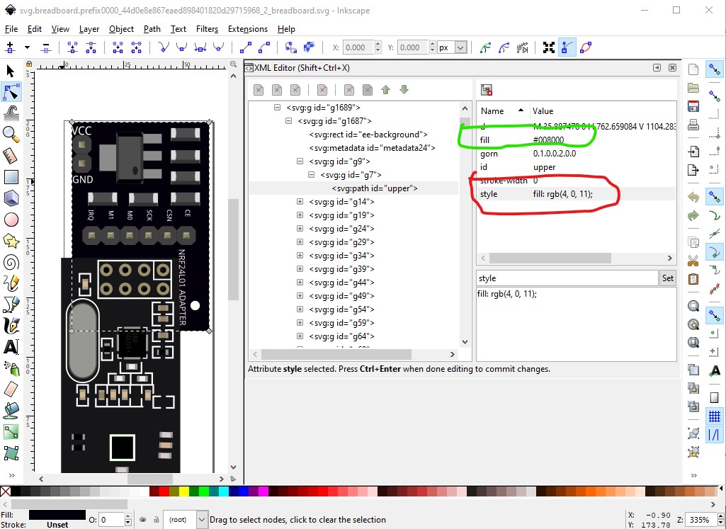
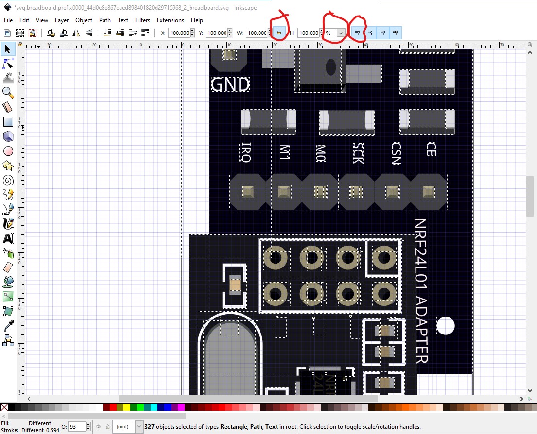
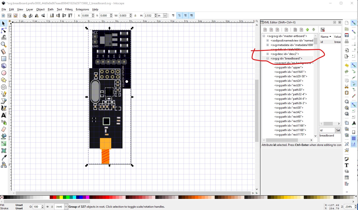
The color problem is that Fritzing is using the fill (green) in the fill attribute (circled in green on the right) Inkscape is using the style command value (black) circled in red on the right. The best cure (and what I did) is run the finished part through FritzingCheckPart.py which is available here:
among other things, it deletes inline parameters like the fill and moves the values in the style command to inline xml (because in some cases, Fritzing does not support style commands!) so both Inkscape and Fritzing are using the same parameters and thus what you see in Inkscape is what you see in Fritzing. Then I noticed the view box is too large because there is an unused path way to the side of the part, so I deleted that to reduce the size of the viewbox to only the part, as it should be.
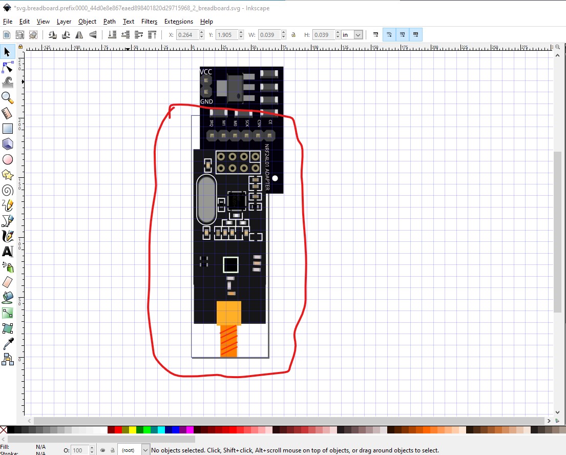
Next the view box doesn’t start at 0 0 (which will cause grid offset issues in Fritzing) so in Inkscape do Edit->select all then Edit->resize page to selection to correct that.
As well the svg is missing the breadboard layerId (which will cause the part to not export as an image) so click Object->group to group the entire image and name the group breadboard. Next FritzingCheckPart.py warned that the drawing is dimensioned in px rather than inches which can (and does in this case!) cause scaling problems.

In this case this didn’t help, because the drawing is in a different dpi than my copy of Inkscape as we will see later but this is how the drawing should be dimensioned.

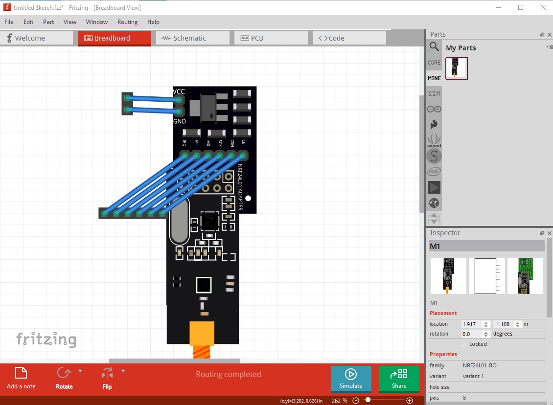
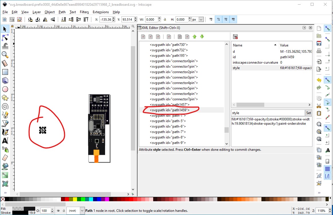
When I saved this breadboard svg, and made a part from it and loaded it in to Fritzing we see the scaling problem.
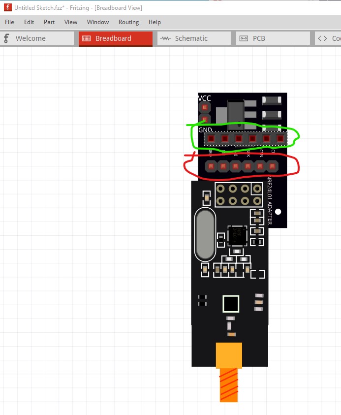
The top connector is a 6pin header dragged in the the sketch from core parts (circled in green) that is correctly aligned on the .1in boundaries. As we see the connector in the part (circled in red) is shorter indicating its scale is incorrect. To fix this I first selected connector1pin whose x coord is 0.219in then selected connector0pin whose x coord is 0.136in (and should be 0.119in to be on a 0.1in boundary.) That means the drawing needs to increase in scale by 120.4819277108434% to make the pins be on 0.1in boundaries. To do that set Inkscape like this:
lock height and width to scale together, change dimensions to percent (all are at present 100%) and enable scale stroke width when scaling (all circled in red above.) Now change the width to
120.4819277108434%
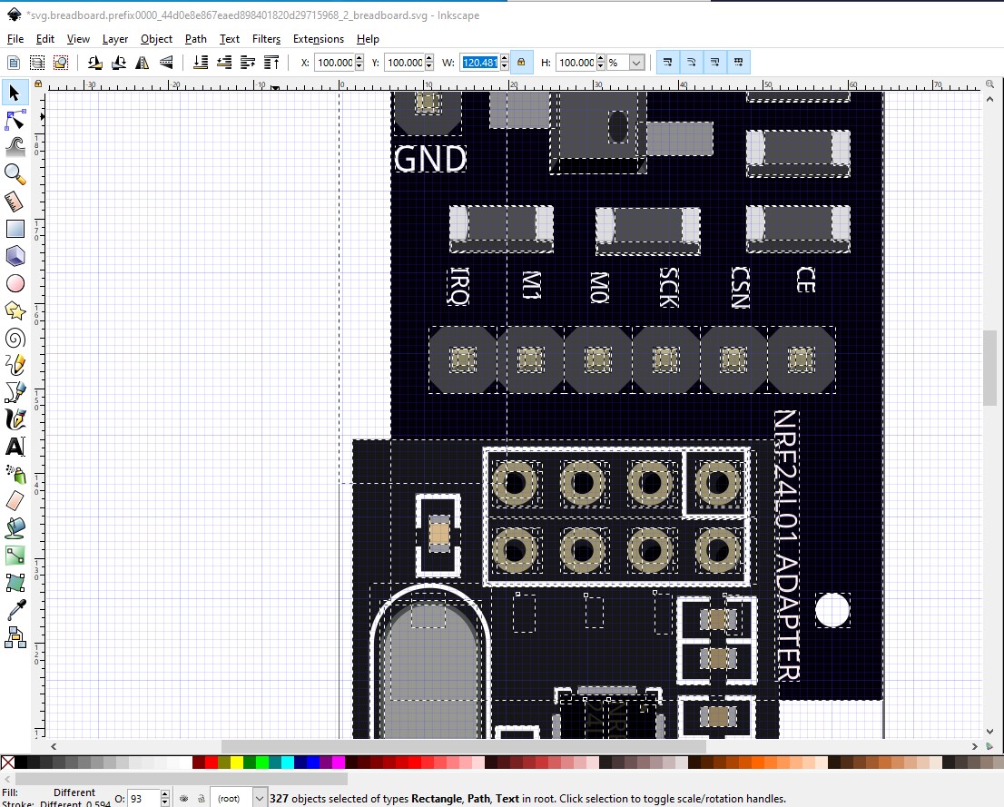
which rescales the drawing so the pins are on .1 in boundaries
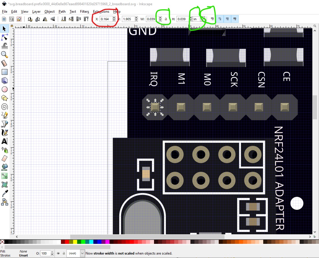
connector0pin is now 0.164in in x
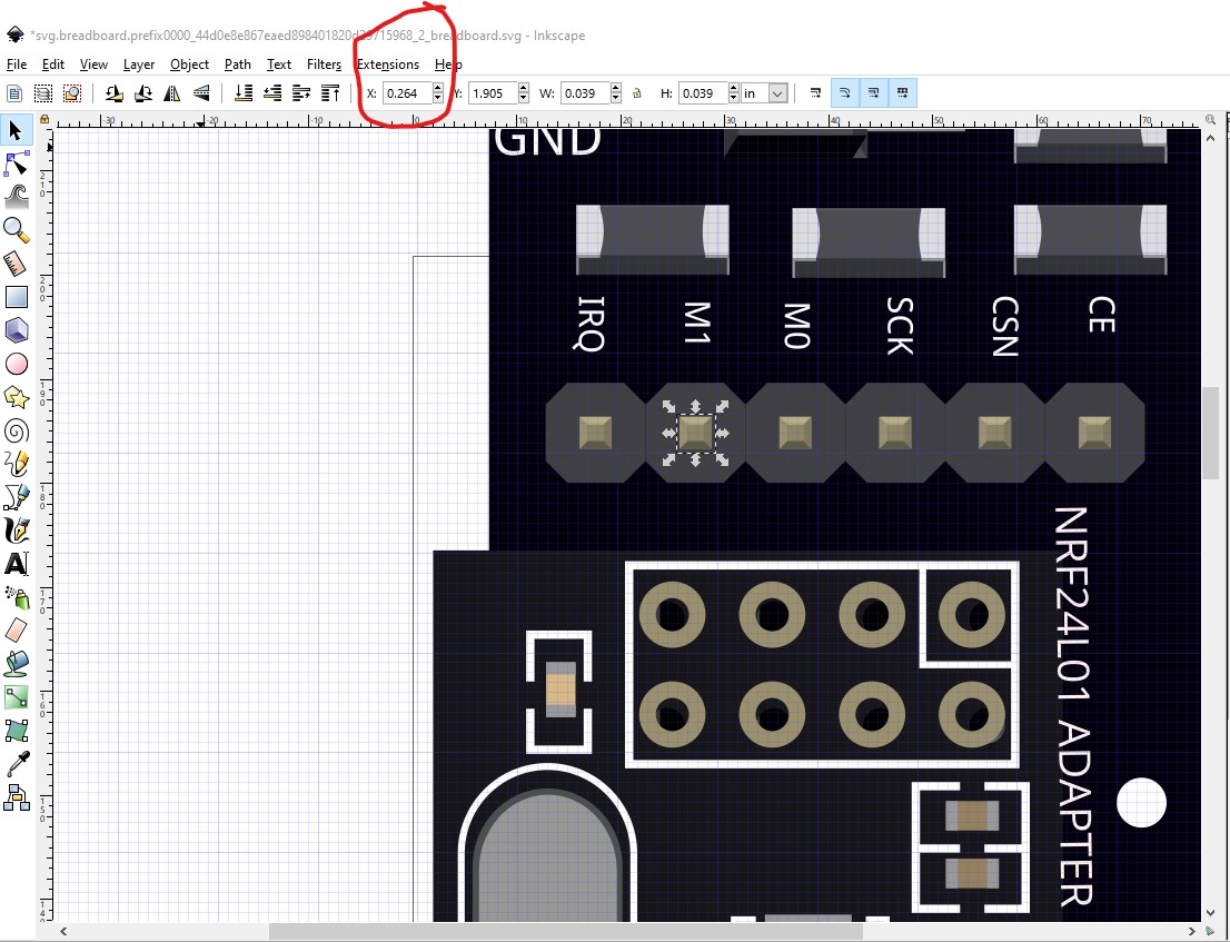
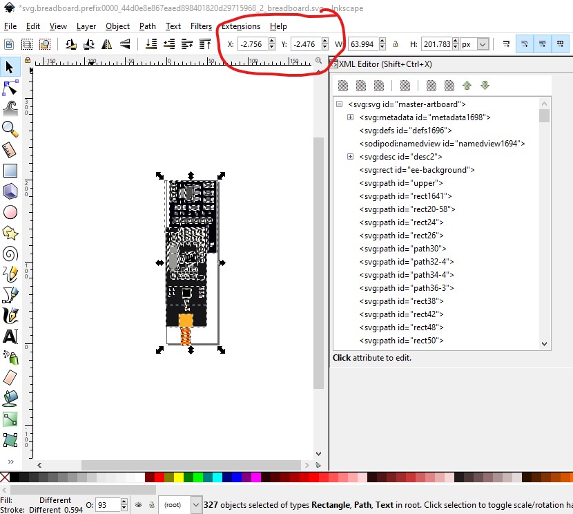
and connector1pin is now 0.264in in x as desired. However because of the rescale, the viewbox is now too small
so do Edit->select all, Edit->resize page to selection and then Object->group and rename the group to breadboard to create a correctly scaled svg with the layerId and save it as plain svg.
Now when I run the part through FritzingCheckPart and zip it to create
NRF24L01-BOv2.0-fixed.fzpz (64.3 KB)
the part is the correct scale in Fritzing (and the correct color!)

Peter
1 Like
thank for this part and help I am use an online svg editor 
Then you need to see if it will let you control the parameters of the svg as Inkscape does. From the documentation (I don’t have Illustrator), I can’t see a way to do this in Illustrator they seem to believe they know best on the svg parameters which can be a problem. Inkscape has its faults, but it is free and flexible enough to do what Fritzing needs. Good luck!
Peter
hello, i used this object for my project, but he doenst have a pcb form. you can help me?
This part should do what you want with a few warnings. There is no mechanical drawing I can find so the pcb pin positions were taken from a jpeg image and thus are likely not accurate. So before ordering boards print the footprint out at 1:1 scale and compare it to a real board (and supply pin position changes if needed!) As well the mounting holes are only in silkscreen. If you want holes drilled on the pcb you need to drag a hole from core parts/pcb in to the sketch, set an appropriate hole size and position it over the hole in silkscreen.
NRF24L01-BO-with-pcb.fzpz (12.3 KB)
Peter
1 Like
thank you very much!
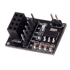
hello, I’m reviving this discussion because I need the fzpz with this image: would you have it please… Indeed, at the bottom of the page is the fzpz available but with the module with the integrated antenna? THANKS
It doesn’t appear there is an individual part for a module with an SMA connector. To make one we would need a web site with the dimensions and connections information for the exact module you want.
Peter
Thanks a lot for your answer
Datasheet nrf24l01+: https://www.handsontec.com/dataspecs/module/NRF24L01+PA.pdf
Datasheet for adapter :
Thanks a lot !![]()
You appear to want just the adapter board, but it is not overly useful as it needs a nrfp24l01 (which the current versions have) to operate. It appears to me that you should use one of the two versions above that include the required nrf24l01 module because the module alone doesn’t do anything. Am I missing something?
Peter
Thank you for your answer. I would like to be able to have the NRP24l01+PA plug on the adapter card as in the drawing above.
Thank you so much
This part in the post above should do what you want as far as I can see. It is the adapter with an SMA connector which appears to be what you want.
Peter
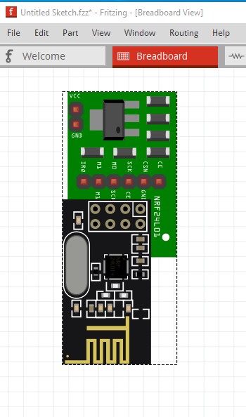
Thank you very much for your response, in fact, I tried a few days ago but it doesn’t seem to work, when I import it doesn’t work…
Try to import it and you will see it doesnt work…![]()