At present there isn’t one it appears (a google search for “fritzijng part Notecarrier F” doesn’t turn one up.) There is this post in their forums that says they are thinking about one from 2022 so you may wish to supply them with one if you complete it.
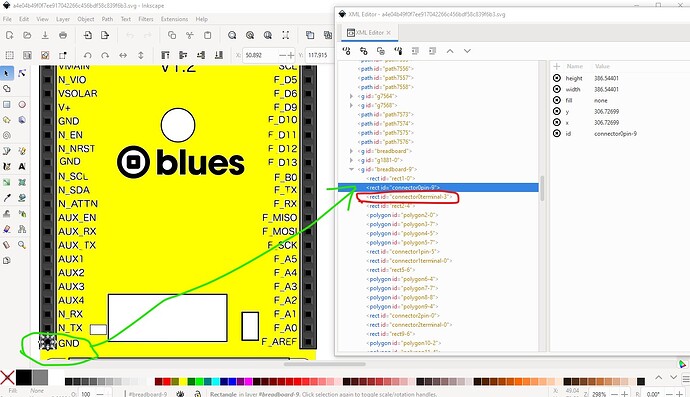
That said your svg has connectors although the grouping and numbering aren’t correct:
You need a group that encloses the entire svg labeled “breadboard” to set the layerId (without it your part won’t export as an image.) I would remove the terminalId (circled in red) as it isn’t needed in breadboard (you need to remove it from the .fzp file if it is in there as well though!) The following tutorial may help you do this:
The likely problem is that the connector numbers don’t match what is defined in the .fzp file and they need to for the connectors to be recognized. This is a snippet of an fzp file with the connector definitions:
      <connector id="connector0" type="male" name="Pin 1">
        <description></description>
        <views>
          <breadboardView>
            <p svgId="connector0pin" layer="breadboard"/>
          </breadboardView>
          <schematicView>
            <p svgId="connector0pin" layer="schematic" terminalId="connector0terminal"/>
          </schematicView>
the labels in your svg need to match the ones in the. .fzp file and likely don’t (connector0pin-9 in the svg file likely isn’t defined in the fzp file and thus isn’t considered a connector.) FritzingCheckPart.py will check your finished part and complain about a variety of errors (in general warnings won’t break a part but errors usually will.) The pins should start at connector0pin on the top left and go up in sequence. Using Randy’s Inkscape schematic extension I would put the left connectors on the left (starts at connector0) then the bottom 2 connectors on the bottom and the right connector on the right with nothing on the top (they need to be in that order for the extension to work correctly.) I have scripts (although not all are published) to renumber pins in the svg if the connectors are the last thing in the svg, again that is covered in the tutorial I think. Schematic is easiest to generate from Randy’s Inkscape Fritzing schematic extension which will produce a properly scaled and configured schematic svg from table input values. It takes a little getting used to, but is far easier than doing it manually. I would likely skip pcb view (how to do that is covered in the tutorial) as it isn’t likely to be useful I don’t think this appears to mostly want connecting wires rather than be intended to mount on a pcb. You have made a good start, but there is a fair way yet to go. Feel free to ask for help if you run in to problems (uploading either the .fzpz file or the svgs preferably so there is something to work from!) which you look to already know how to do.
Peter
