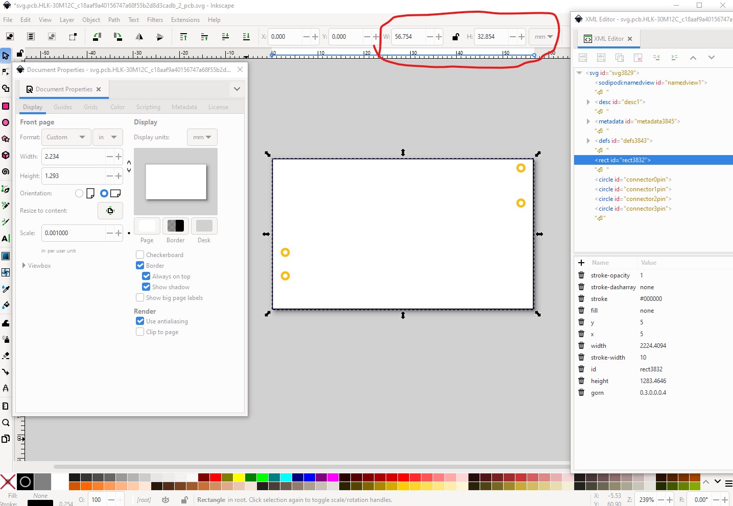
There isn’t an online version that I am aware of, it usually runs without much problem (the lack of lxml is usually the problem and that can be cured with pip) but it normally gives more error information than just “SyntaxError: invalid syntax” (but I am on Windows not a Mac, so things may be different there.) One thing to try is run it as FritzingCheckPart.py -d3 part.HLK-part.fzp (the file name should be .fzp not the .fzpz file which is compressed.) The directory with the part should look like this with the .fzp file and all the svgs present.
part.24V_SMD2835_LED_Strip_1.fzp
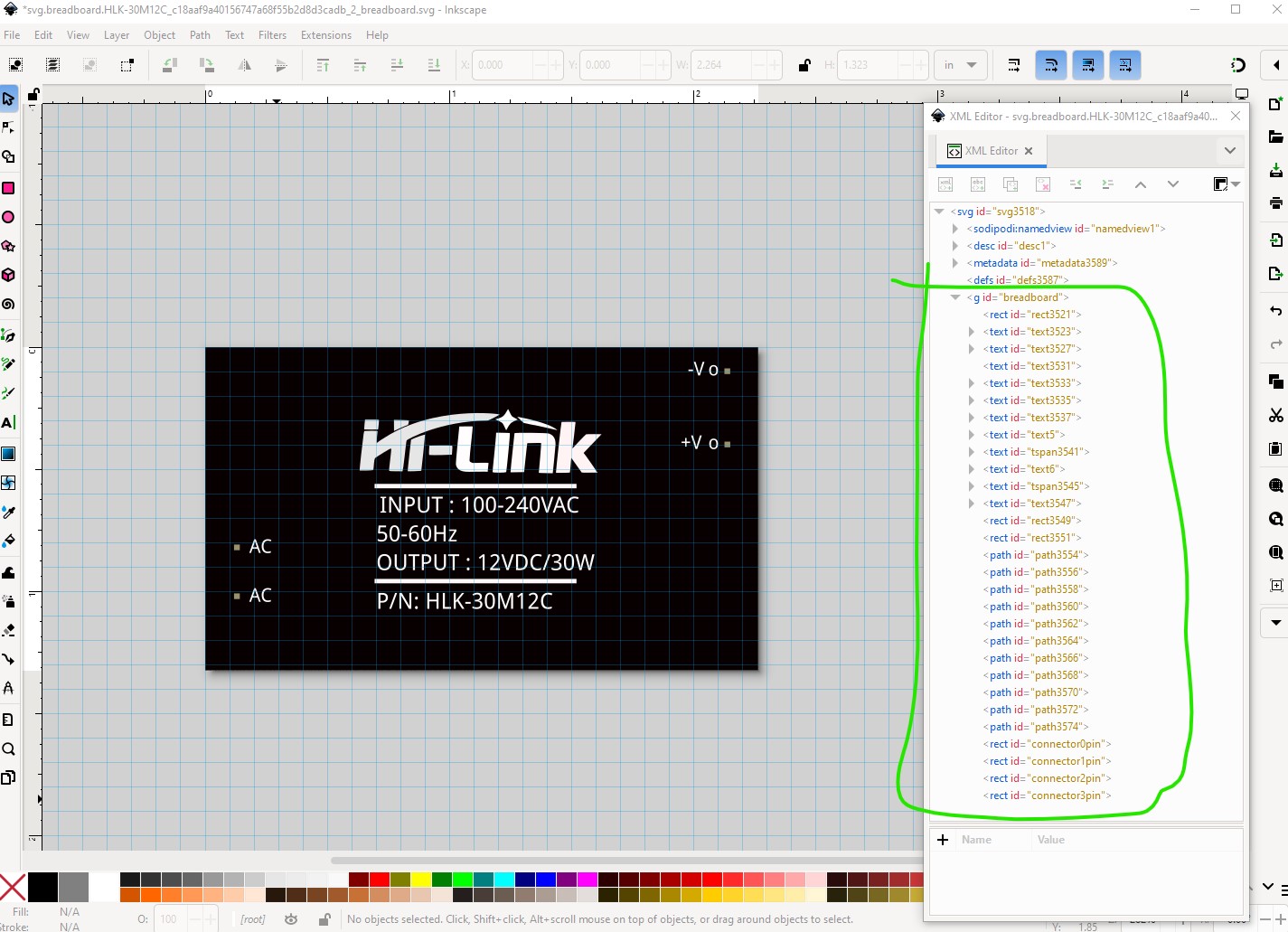
svg.breadboard.prefix0000_6fbdb41430491ba080df8d6e0bc872e1_11_breadboard.svg
svg.icon.prefix0000_6fbdb41430491ba080df8d6e0bc872e1_11_icon.svg
svg.pcb.prefix0000_6fbdb41430491ba080df8d6e0bc872e1_11_pcb.svg
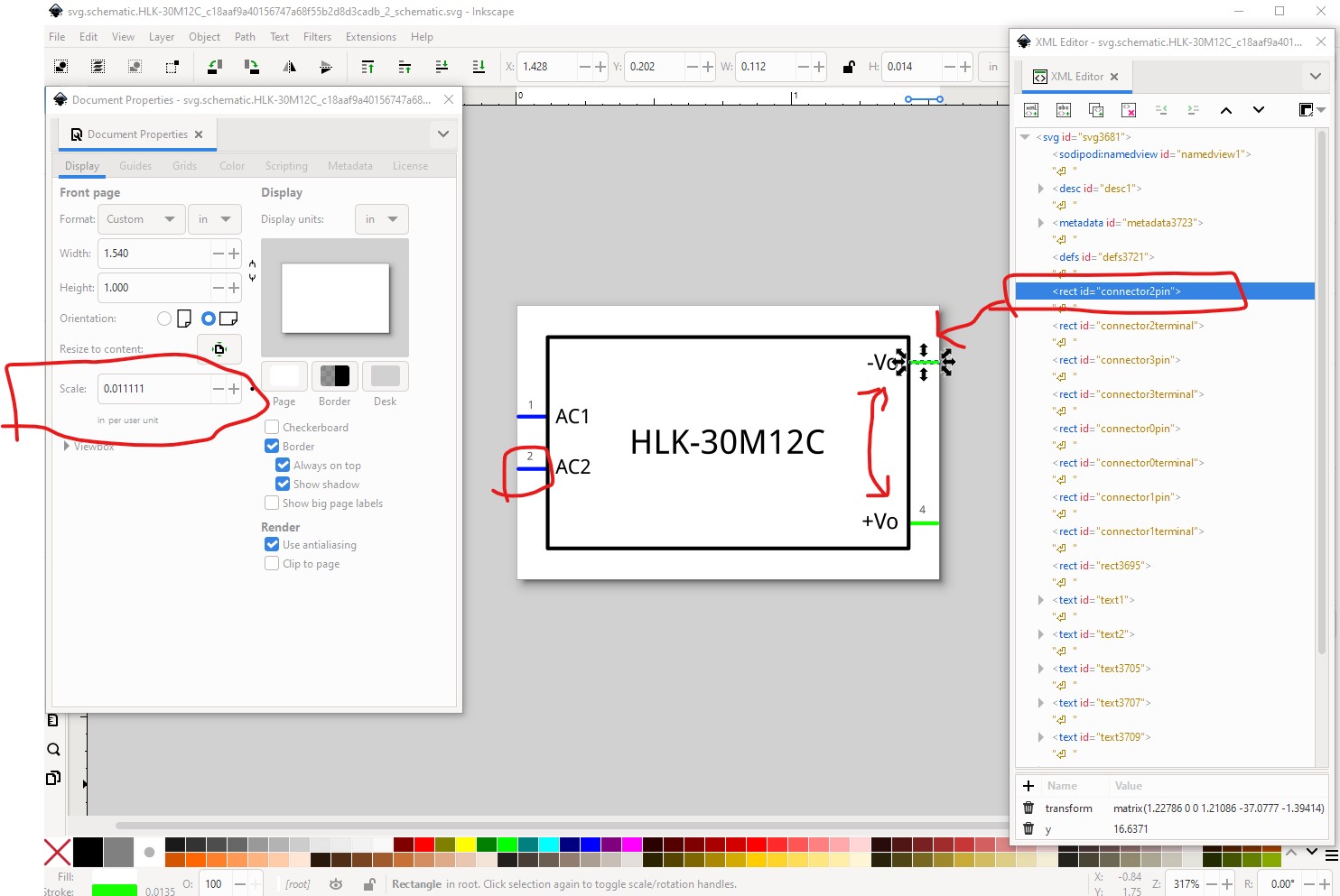
svg.schematic.prefix0000_6fbdb41430491ba080df8d6e0bc872e1_11_schematic.svg
The -d3 activates debug mode which should produce a bunch of debug information on the console and may tell me something. Alternately and maybe easiest if you upload your .fzpz file (upload is 7th icon from the left in the reply menu.) I can download it, decompress it and run it through FritzingCheckPart.py to both check it and show you what kind of output you should be expecting and what to do about any errors.
edit:
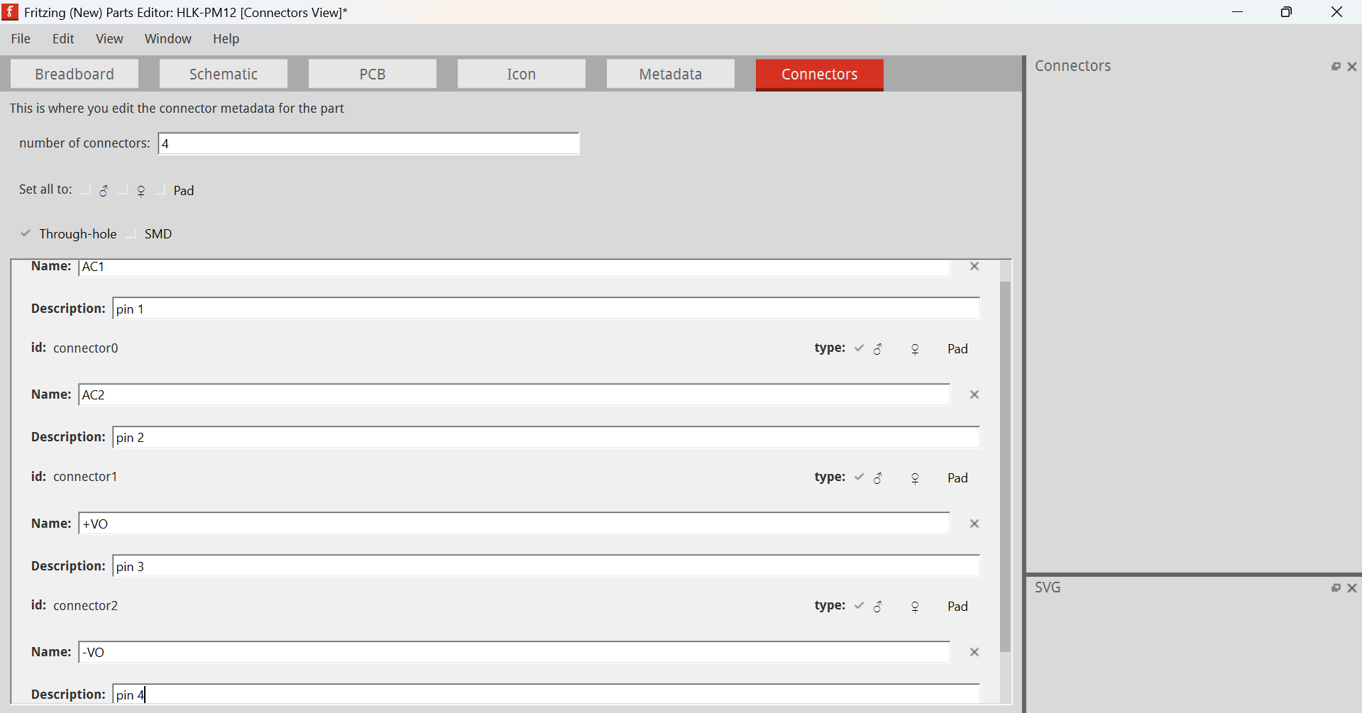
I just downloaded your part above and ran it with this result
$ FritzingCheckPartw.py part.HLK-10M05_7db924165e20438e5ba65929091a3343_2.fzp
**** Starting to process file Startup, no file yet
**** Starting to process file part.HLK-10M05_7db924165e20438e5ba65929091a3343_2.fzp
**** Starting to process file svg.breadboard.HLK-10M05_7db924165e20438e5ba65929091a3343_2_breadboard.svg.bak
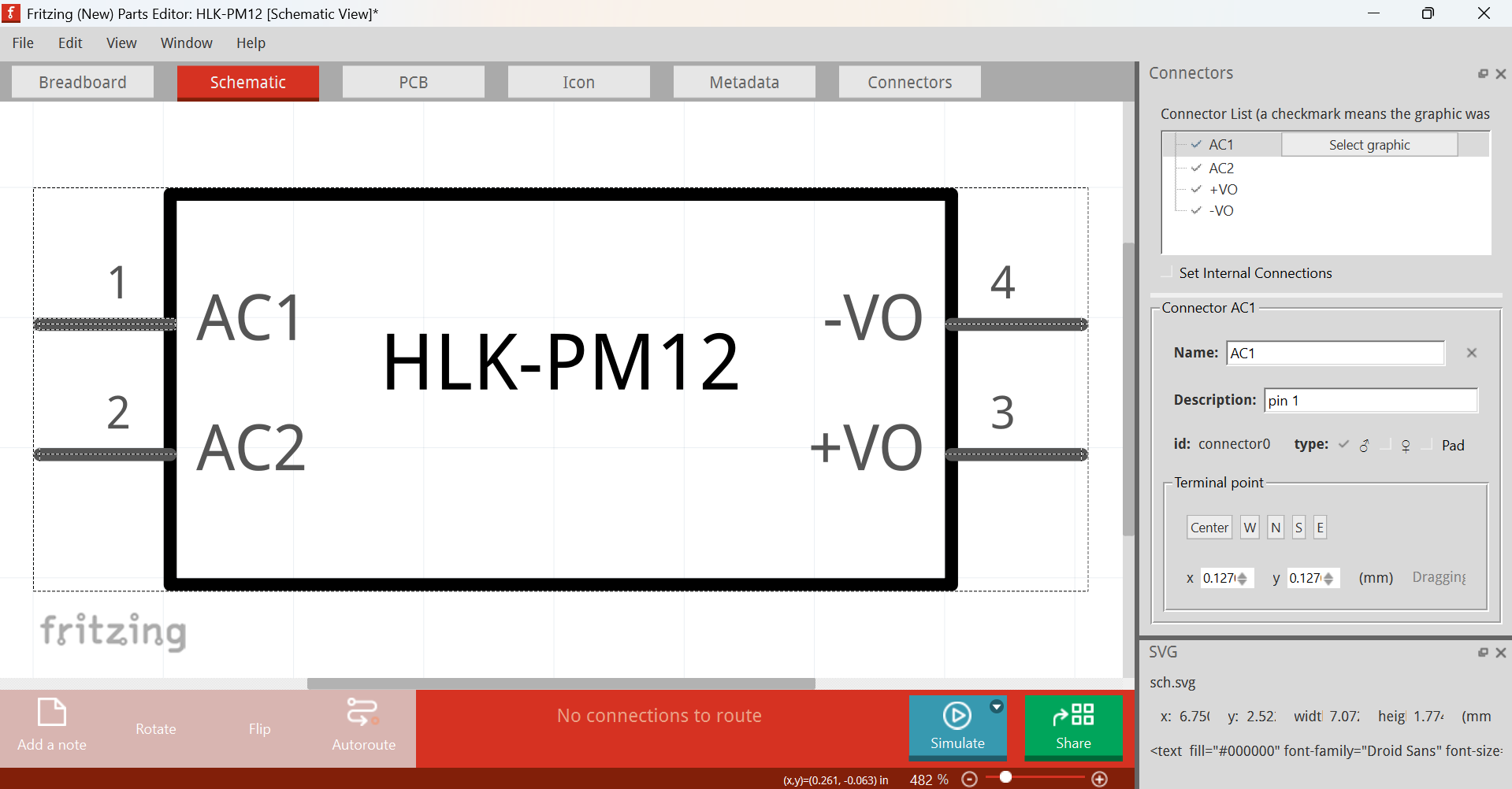
**** Starting to process file svg.schematic.HLK-10M05_7db924165e20438e5ba65929091a3343_2_schematic.svg.bak
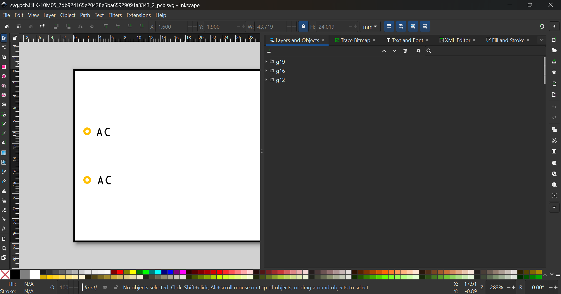
**** Starting to process file svg.pcb.HLK-10M05_7db924165e20438e5ba65929091a3343_2_pcb.svg.bak
File
‘part.HLK-10M05_7db924165e20438e5ba65929091a3343_2.fzp.bak’
This is a through hole part as both copper0 and copper1 views are present.
If you wanted a smd part remove the copper0 definition from line 47
Modified 4: File
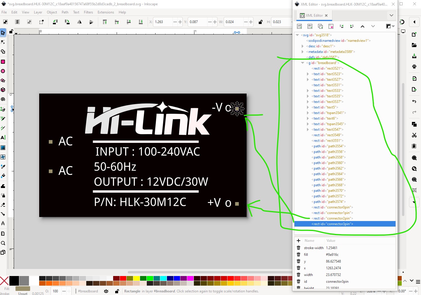
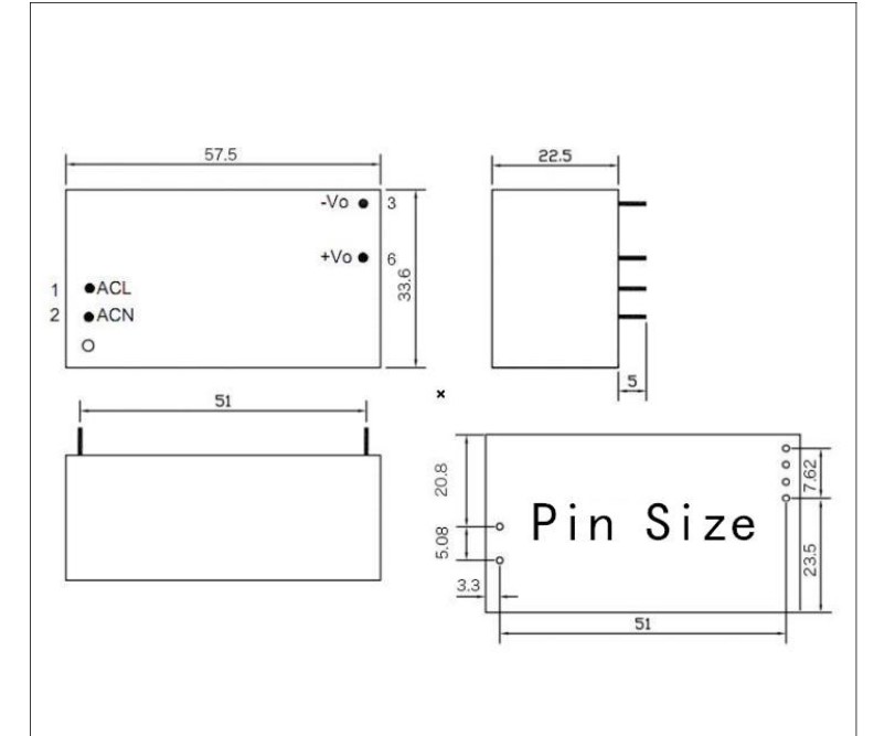
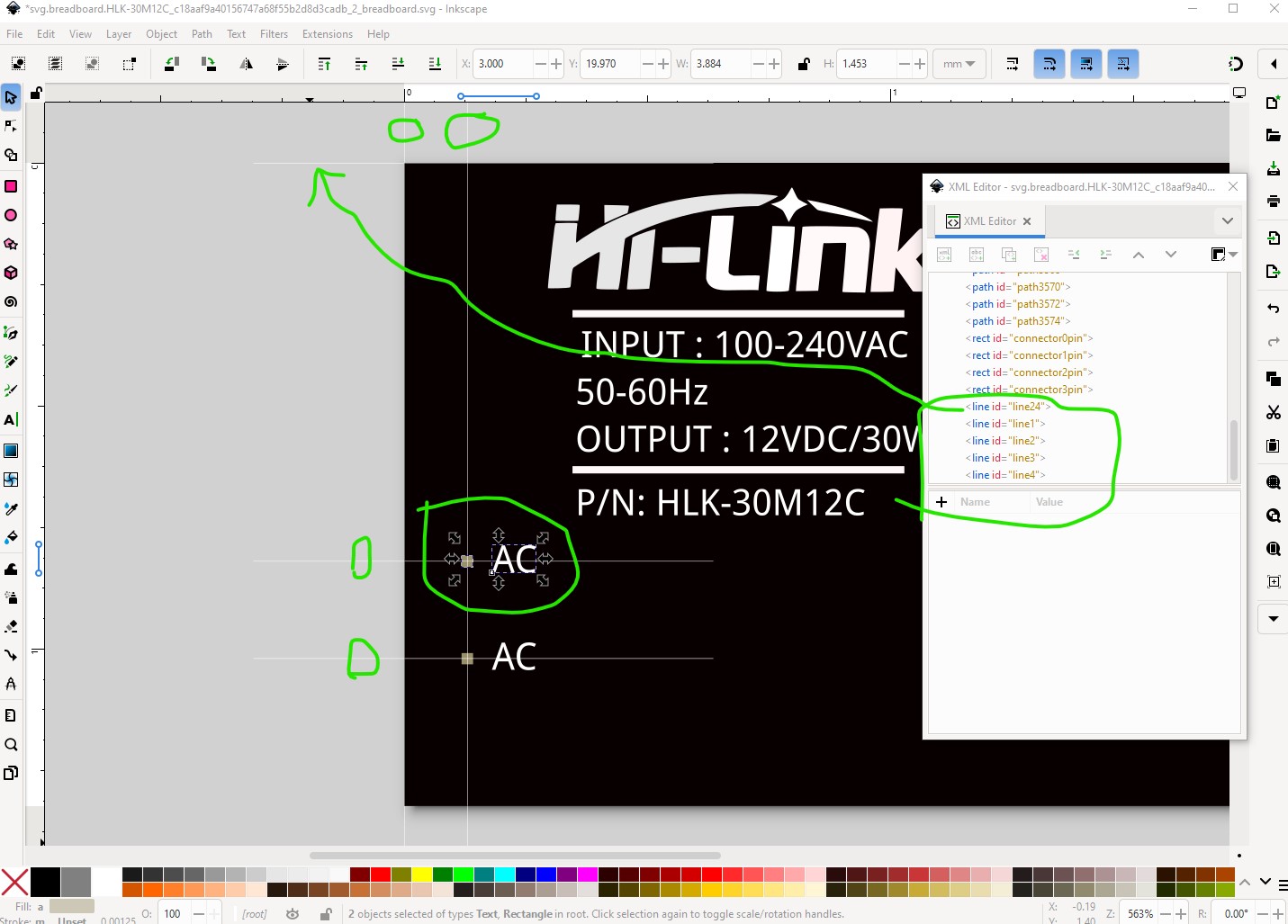
‘svg.breadboard.HLK-10M05_7db924165e20438e5ba65929091a3343_2_breadboard.svg.bak’
At line 4
ReferenceFile
‘HLK-PM01-Breadboard.svg’
doesn’t match input file
‘HLK-10M05_7db924165e20438e5ba65929091a3343_2_breadboard.svg’
Corrected
Modified 1: File
‘svg.breadboard.HLK-10M05_7db924165e20438e5ba65929091a3343_2_breadboard.svg.bak’
At line 28
Removed px from font-size leaving 5.56692982
Modified 1: File
‘svg.breadboard.HLK-10M05_7db924165e20438e5ba65929091a3343_2_breadboard.svg.bak’
At line 45
Removed px from font-size leaving 6
Modified 1: File
‘svg.breadboard.HLK-10M05_7db924165e20438e5ba65929091a3343_2_breadboard.svg.bak’
At line 48
Removed px from font-size leaving 6
Modified 1: File
‘svg.breadboard.HLK-10M05_7db924165e20438e5ba65929091a3343_2_breadboard.svg.bak’
At line 49
Removed px from font-size leaving 6
Modified 1: File
‘svg.breadboard.HLK-10M05_7db924165e20438e5ba65929091a3343_2_breadboard.svg.bak’
At line 50
Removed px from font-size leaving 6
Modified 1: File
‘svg.breadboard.HLK-10M05_7db924165e20438e5ba65929091a3343_2_breadboard.svg.bak’
At line 51
Removed px from font-size leaving 6
Modified 1: File
‘svg.breadboard.HLK-10M05_7db924165e20438e5ba65929091a3343_2_breadboard.svg.bak’
At line 68
Removed px from font-size leaving 5.56692982
Modified 4: File
‘svg.schematic.HLK-10M05_7db924165e20438e5ba65929091a3343_2_schematic.svg.bak’
At line 4
ReferenceFile
‘HLK-PM01-Schematic.svg’
doesn’t match input file
‘HLK-10M05_7db924165e20438e5ba65929091a3343_2_schematic.svg’
Corrected
Modified 1: File
‘svg.schematic.HLK-10M05_7db924165e20438e5ba65929091a3343_2_schematic.svg.bak’
At line 38
Removed px from font-size leaving 5.94430017
Modified 1: File
‘svg.schematic.HLK-10M05_7db924165e20438e5ba65929091a3343_2_schematic.svg.bak’
At line 42
Removed px from font-size leaving 5.94430017
Modified 1: File
‘svg.schematic.HLK-10M05_7db924165e20438e5ba65929091a3343_2_schematic.svg.bak’
At line 46
Removed px from font-size leaving 9.0708704
Modified 1: File
‘svg.schematic.HLK-10M05_7db924165e20438e5ba65929091a3343_2_schematic.svg.bak’
At line 47
Removed px from font-size leaving 5.45108986
Modified 1: File
‘svg.schematic.HLK-10M05_7db924165e20438e5ba65929091a3343_2_schematic.svg.bak’
At line 48
Removed px from font-size leaving 5.45108986
Modified 1: File
‘svg.schematic.HLK-10M05_7db924165e20438e5ba65929091a3343_2_schematic.svg.bak’
At line 49
Removed px from font-size leaving 3
Modified 1: File
‘svg.schematic.HLK-10M05_7db924165e20438e5ba65929091a3343_2_schematic.svg.bak’
At line 50
Removed px from font-size leaving 3
Modified 1: File
‘svg.schematic.HLK-10M05_7db924165e20438e5ba65929091a3343_2_schematic.svg.bak’
At line 51
Removed px from font-size leaving 3
Modified 1: File
‘svg.schematic.HLK-10M05_7db924165e20438e5ba65929091a3343_2_schematic.svg.bak’
At line 52
Removed px from font-size leaving 3
Modified 4: File
‘svg.pcb.HLK-10M05_7db924165e20438e5ba65929091a3343_2_pcb.svg.bak’
At line 5
ReferenceFile
‘5 volt voeding new.svg’
doesn’t match input file
‘HLK-10M05_7db924165e20438e5ba65929091a3343_2_pcb.svg’
Corrected
Warning 6: File
‘part.HLK-10M05_7db924165e20438e5ba65929091a3343_2.fzp.bak’
At line 2
ReferenceFile name
‘generic_ic_dip_4_300mil.fzp’
Doesn’t match fzp filename
‘HLK-10M05_7db924165e20438e5ba65929091a3343_2.fzp’
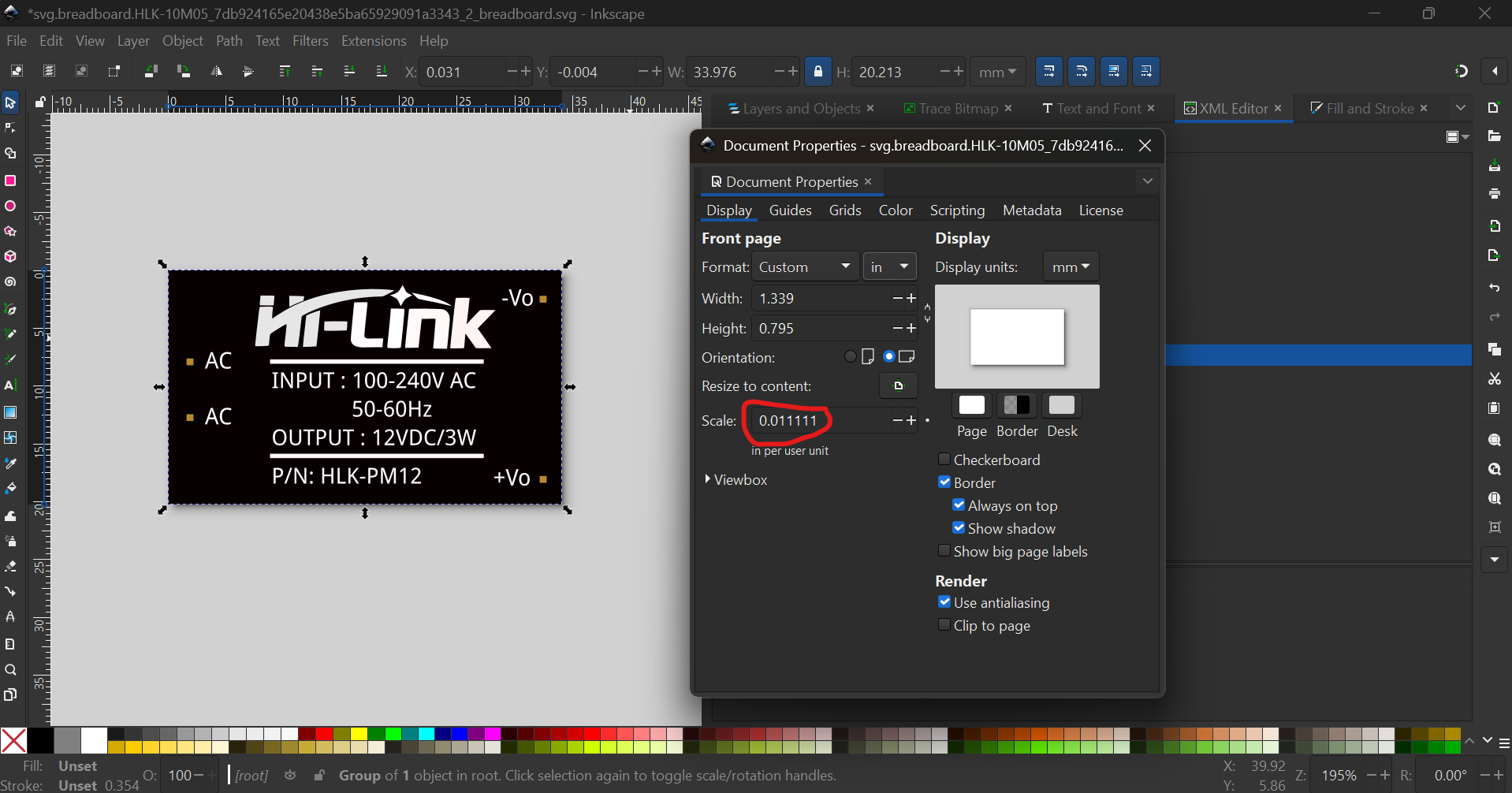
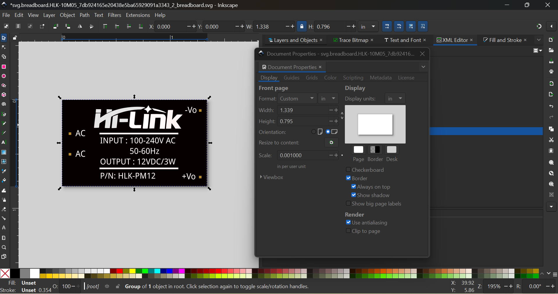
Warning 32: File
‘svg.breadboard.HLK-10M05_7db924165e20438e5ba65929091a3343_2_breadboard.svg.bak’
At line 2
Scale is not the desirable 1/1000 ratio from width/height to
viewBox width/height.
Warning 23: File
‘svg.breadboard.HLK-10M05_7db924165e20438e5ba65929091a3343_2_breadboard.svg.bak’
At line 97
Key -inkscape-font-specification
value Droid Sans is invalid and has been deleted
Warning 32: File
‘svg.schematic.HLK-10M05_7db924165e20438e5ba65929091a3343_2_schematic.svg.bak’
At line 2
Scale is not the desirable 1/1000 ratio from width/height to
viewBox width/height.
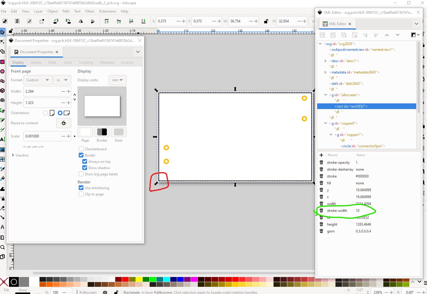
Warning 32: File
‘svg.pcb.HLK-10M05_7db924165e20438e5ba65929091a3343_2_pcb.svg.bak’
At line 3
Scale is not the desirable 1/1000 ratio from width/height to
viewBox width/height.
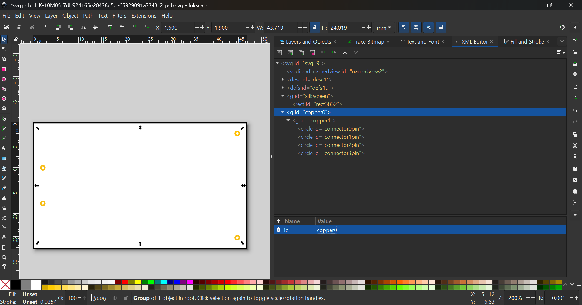
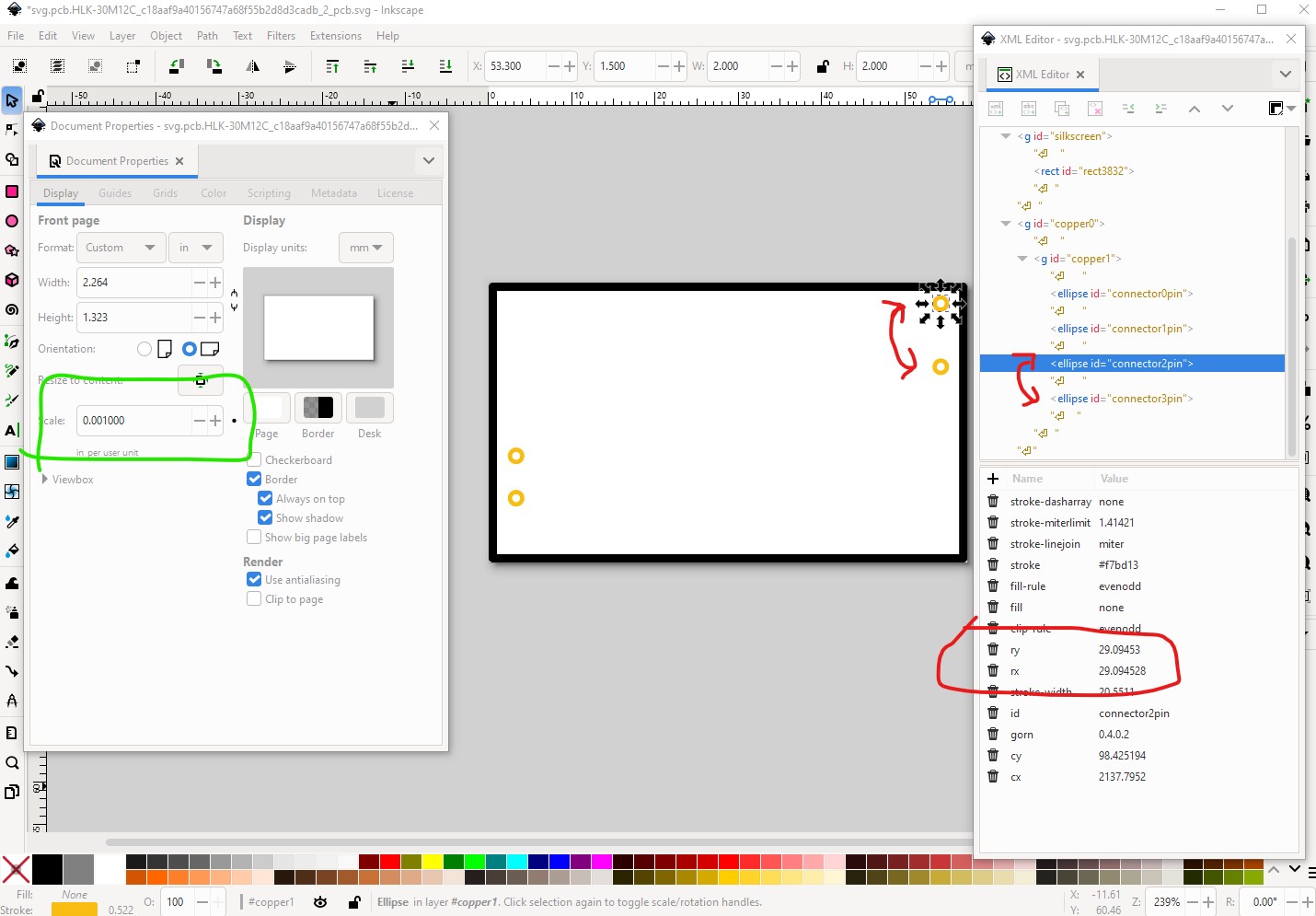
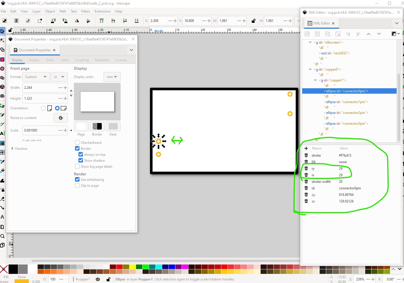
Warning 25: File
‘svg.pcb.HLK-10M05_7db924165e20438e5ba65929091a3343_2_pcb.svg.bak’
At line 30
Silkscreen layer should be above the copper layers for easier selection
in pcb view
Warning 23: File
‘svg.pcb.HLK-10M05_7db924165e20438e5ba65929091a3343_2_pcb.svg.bak’
At line 33
Key -inkscape-font-specification
value OCRA is invalid and has been deleted
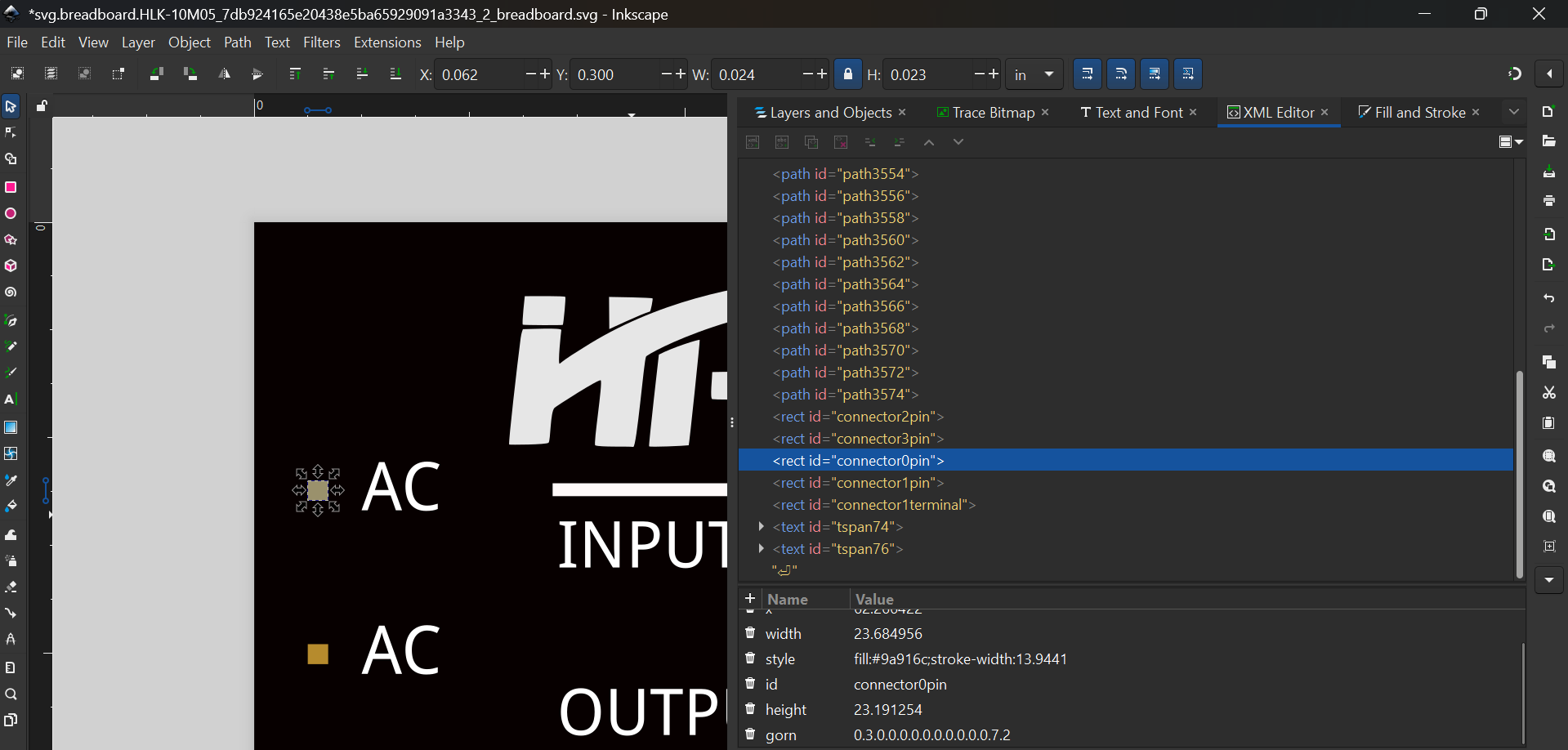
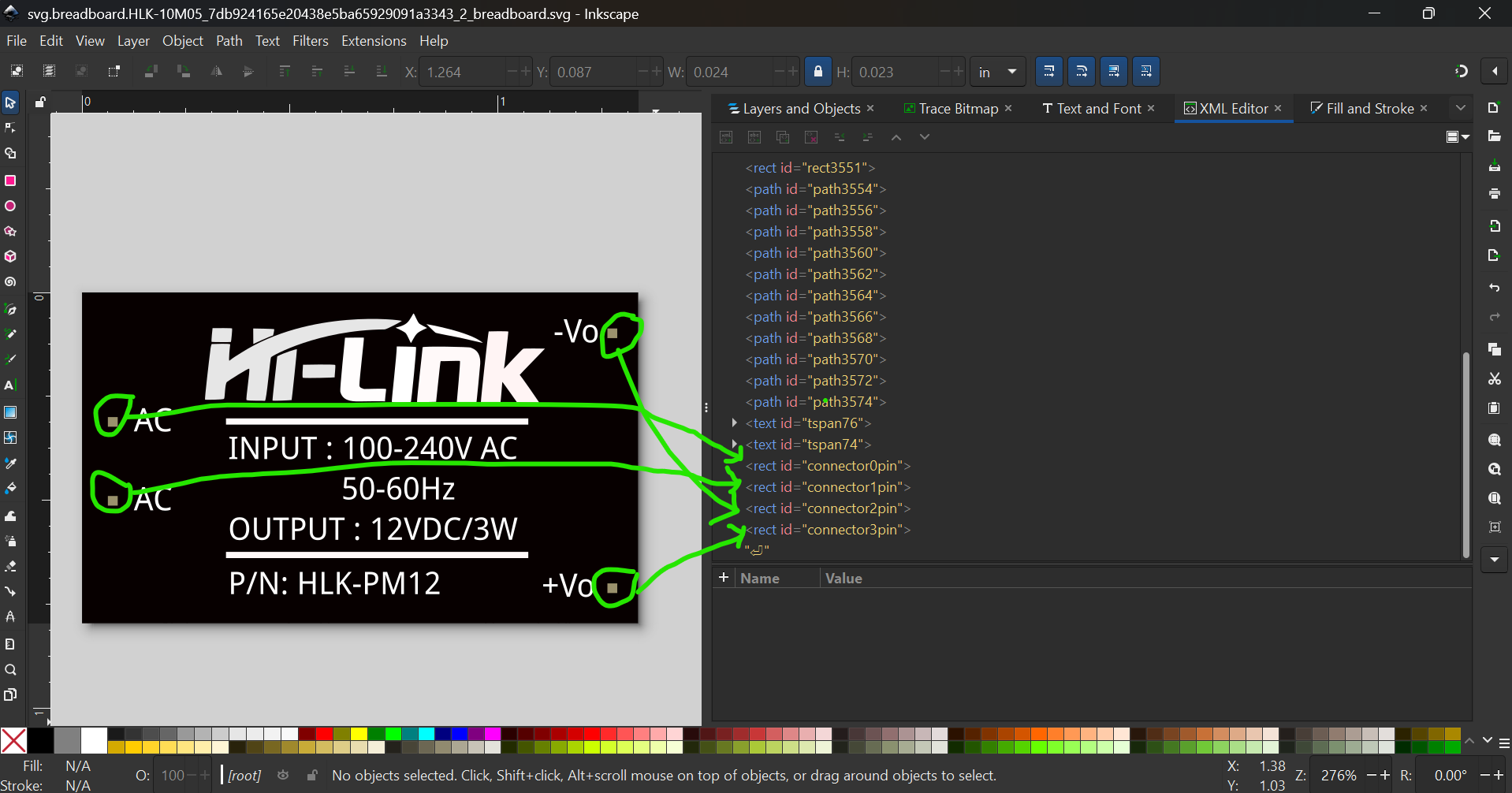
Error 18: File
‘part.HLK-10M05_7db924165e20438e5ba65929091a3343_2.fzp.bak’
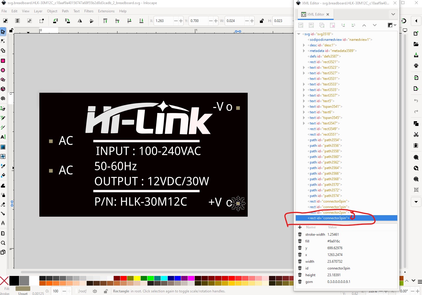
Connector connector0terminal is in the fzp file but not the svg file. (typo?)
svg svg.breadboard.HLK-10M05_7db924165e20438e5ba65929091a3343_2_breadboard.svg.bak
Error 18: File
‘part.HLK-10M05_7db924165e20438e5ba65929091a3343_2.fzp.bak’
Connector connector2terminal is in the fzp file but not the svg file. (typo?)
svg svg.breadboard.HLK-10M05_7db924165e20438e5ba65929091a3343_2_breadboard.svg.bak
Error 18: File
‘part.HLK-10M05_7db924165e20438e5ba65929091a3343_2.fzp.bak’
Connector connector3terminal is in the fzp file but not the svg file. (typo?)
svg svg.breadboard.HLK-10M05_7db924165e20438e5ba65929091a3343_2_breadboard.svg.bak
Error 69: File
‘svg.schematic.HLK-10M05_7db924165e20438e5ba65929091a3343_2_schematic.svg.bak’
At line 28
Found a drawing element before a layerId (or no layerId)
another thought are you running python3? I’m not sure FritzingCheckPart.py will run on python2.x although it may.
edit2:
I modified a test script to have a syntax error then ran it. For me here is the output it produces:
$ FritzingCheckPartt.py part.HLK-10M05_7db924165e20438e5ba65929091a3343_2.fzp
FritzingCheckPart.py: Starting to process file
Startup, no file yet
INFO: FritzingToolst.py line 152
Entering ProcessArgs
INFO: FritzingToolst.py line 339
Exiting ProcessArgs
Traceback (most recent call last):
File “/usr/local/bin/FritzingCheckPartt.py”, line 352, in
Fritzing.OutputSplashScreent(InFile, Debug)
AttributeError: module ‘FritzingToolst’ has no attribute ‘OutputSplashScreent’
I would expect to see more information than just a syntax error with no context, python normally provides detailed error messages as it did here.
Peter