I am working on a water valve that I can open remotely. I have a buck converter to bring the voltage down for the pico w. I’m trying to lighten the weight, I don’t see a power bank to use in fritzing. Any suggestions? Anyone looking at my work and giving me improvements are much appreciated.
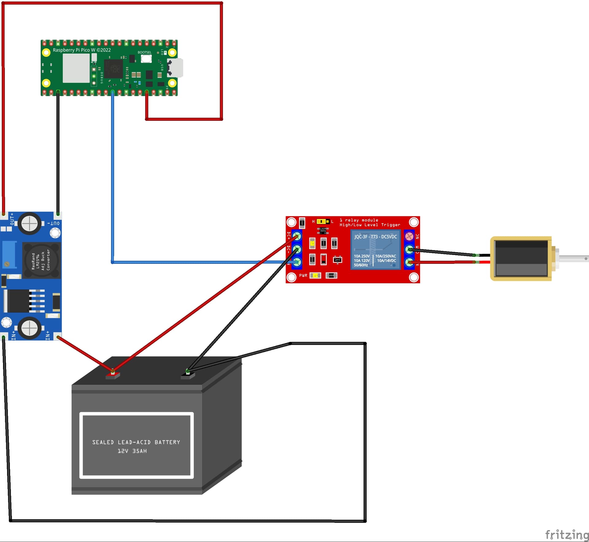
As it stands this likely won’t work. There is no source of power for the valve. The three relay terminals on the right connecting to the valve need power to work they are only a switch (and the VCC on the left should likely be the same as is applied to the Pico not 12V!) It isn’t clear what a power bank may be to say whether there is a Fritzing part for it or not. A data sheet or web site describing what you want would be a good start. Assuming you are driving this off battery as indicated you would also need a charging circuit and source of power to do the charging. Basically there isn’t enough information here to say more …
Peter
I’m still learning how to use the software. I’ve made some changes. I was speaking of replacing the 12 volt battery with a battery brick that has usb ports. Adding a solar cell and related circuit to maintain the charge on the bank. Something like this power bank.
This Adafruit part is likely as close as there is.
(from a google search of the form “fritzing part Portable-Charger-Power-Bank”.) There are a variety of solar charger parts available in the forums (people have asked for them over the years.) That said your circuit still will not work. The relay module only provides a switch function, it does not supply any power on the contacts. Without a power source the solenoid valve will not function and thus as it stands this sketch will not work.
Peter
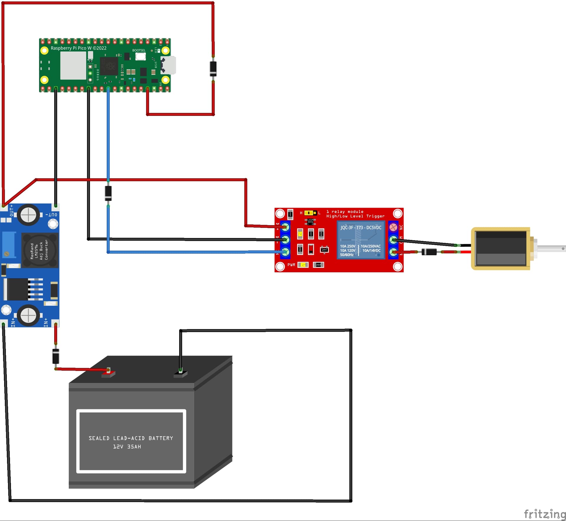
Thanks for your feedback! I’ve been looking over my sketch and I see what your saying. I’ve been starting at the battery. Going backwards I see where I messed up. I uploaded another version I think I’ve thought it through. Your feed back is always welcome.
That will work better, however you don’t need (and probably don’t want) the diodes in series with the valve. Putting a reverse diode across the valve solenoid coil would be a good bet to give the coil back EMF a discharge path though. There are smaller versions of buck converter, but I expect the weight of the battery pack is going far outweigh any weight saving from the buck converter.
Peter
I removed the diodes. I just realized that the solenoid will not work with 5 volts it works with 12 to 24 volts. The battery is just there as reference. I have a solar cell JL04555, 1pc 12v 18v Solarpanel Mit Batterieclip Und 20a Solarautoladegerät Controller Wasserdichte Solarzellen Für Outdoor Camping Wandern - Terrasse, Garten & Rasen - Temu Germany , and use it for charging 18650 battery pack. It’s a process but if it works it will be a time saver.
A boost converter will boost the 3.7V LIPO output to 12 or 24V but at the cost of input current. You need to figure out how much current the solenoid valve takes (some I have take 100MA at 12V which translates to about 250MA at 3.7V from a LIPO) and if they are available open if unpowered or closed if unpowered. Then you need to figure out which is going to be the most common state (valve open or valve closed) and select the valve appropriately to minimize current draw. You want to reduce the average current draw as far as possible (which may be easier with a different CPU board, some of the bluetooth type CPUs are lower power!) to preserve battery life.
Peter
1 Like
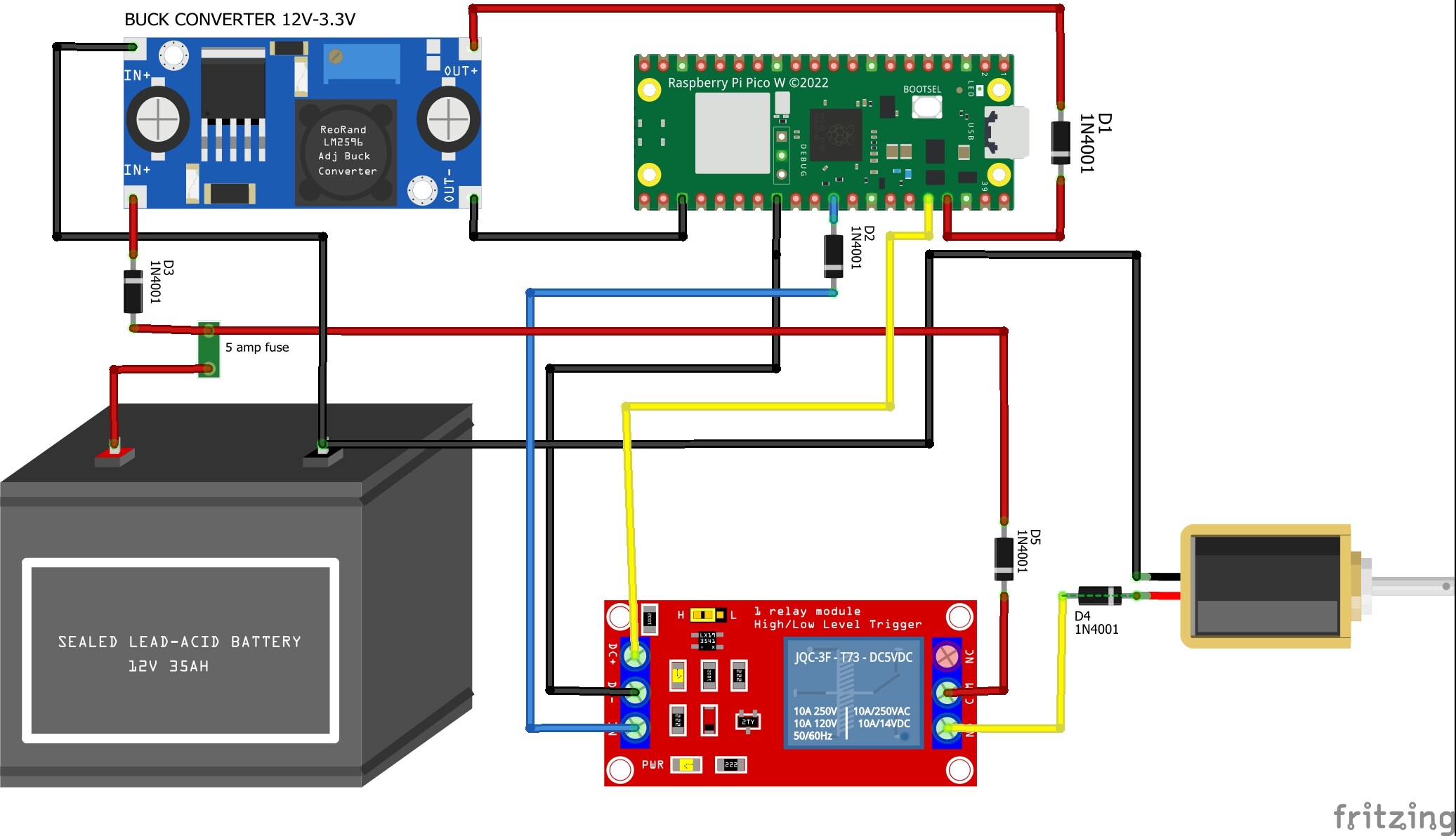
The controller is not rated for LIPO batteries, so I’m sticking with a small 12 7ah battery. I will be powering the pico via the usb port. I think I have it covered. What do you think vanepp?
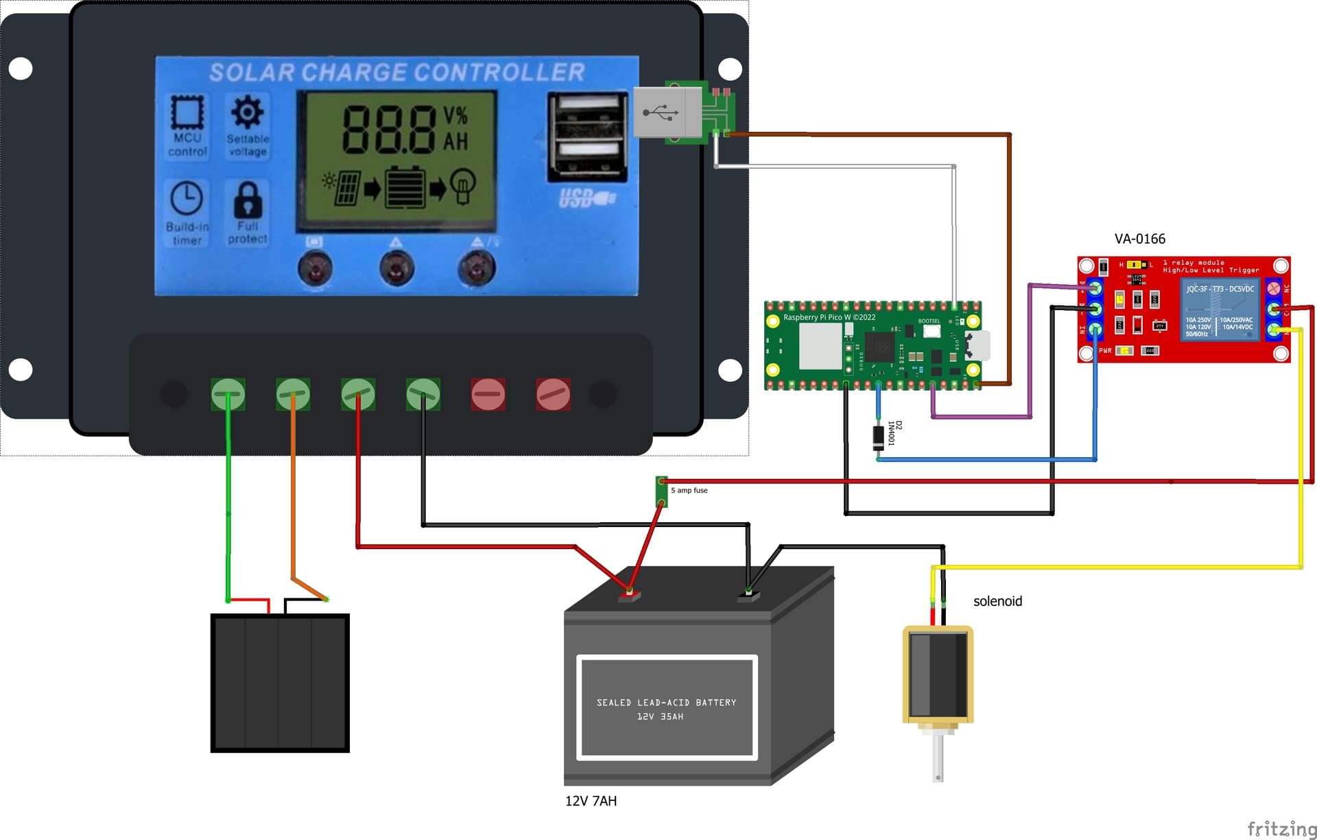
This should work I expect. The diode in the signal lead is redundant and only degrades noise immunity so I would remove it. Given you are running on battery and solar charging I would replace the relay with a power fet switch module. Saves around 100MA (as I recall) of current in the relay coil (you need a back EMF diode across the FET because of the inductive load of the solenoid though!) and look at using a lower power CPU. In battery systems power is your enemy and you want to reduce it as far as possible with tricks like letting the CPU sleep when it doesn’t need to do anything, selecting a low power CPU board and selecting the lowest power option for the valve that you can find consistent with the pressure it needs to switch. All of that increases your battery life before recharge which is usually the important parameter. More current draw reduces the time the system can operate without sunlight to charge the battery (which may or may not be a problem in your case.) You need to balance the cost of minimizing the current draw (and increasing battery life) against the cost of failure of the system if the battery fails due to lack of sun light.
Peter