As a beginner I am having a hard time trying to understand circuit schemes. I want to write one for my project for learning purposes. I’ve build Arduino Uno clock with LCD display and RTC module. As mentioned in the title - it is powered by power bank connected to USB port. I have no idea how to present it on a circuit diagram. Help would be highly appreciated!
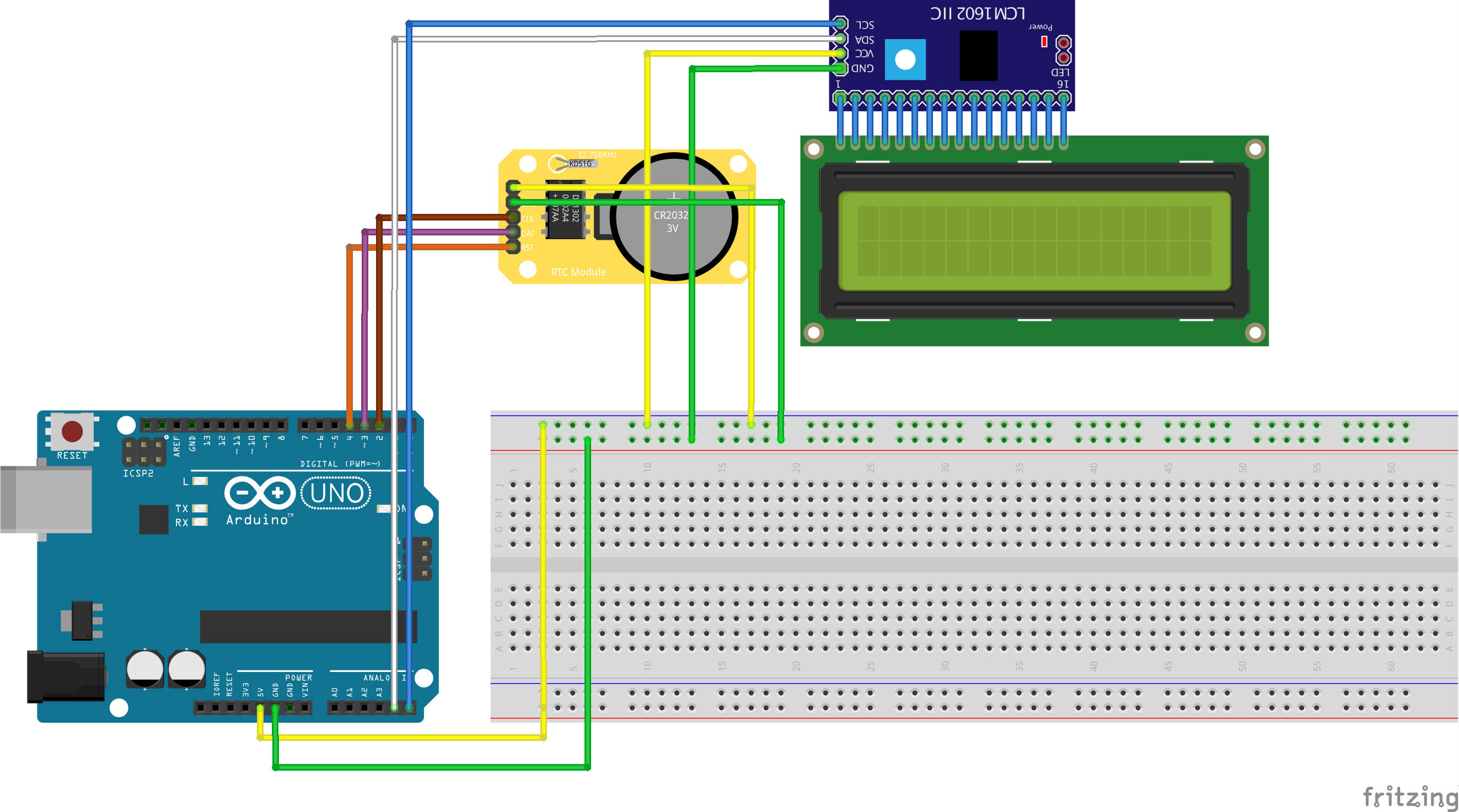
Sketch of my project:
This fritzing part from Adafruit may be as close as you come. I assume your power bank is a battery and regulator with a usb cable output and this does the same thing, it may just not look quite the same.
Otherwise you likely need a custom Fritzing part which would require the data sheet for the power bank you have (I don’t see any power bank Fritzing parts other than the Adafruit one at present.)
You can also “represent” your power bank by using the existing “battery holder” part. Search for “battery” then look for the picture with 2 AA batteries in a holder. Place that on the breadboard view, make sure the holder is selected, then in Inspector set it to 4.8V.
The Arduino board (part) does not have electrical connectors for the USB port. Connect your battery to GND and 5V pins to get the matching electrical connections.
We really should have a generic battery holder / board / power source with a USB connector. Would still need to connect to the GND and 5V pins, unless also modify the Arduino board part to have electrical connections on the USB port.
Female USB breakout board with both breakout and on physical connector connectors, with bus between. All connectors female. Variations by USB type (A,micro,min)
Position that over the (connectorless) USB port on an arduino (or other) board, and wire the breakout side to the matching pins on the Arduino.
Male USB breakout board with both breakout and on physical connector connectors, with bus between. At least the physical connectors male. This can ‘drop’ onto the above Female USB connector, then the breakout side can be connected a battery bank, holder, or power supply, including one on a PCB or breadboard.
On schematic, both of those are simple headers. With the buses, do not even need to double the pins. Can either ignore the PCB, or represent as the header for the breakout side. Equivalent to mounting on, or wiring the USB connector to the PCB.