I cannot start new parts editor:
I downloaded latest version 64bit for windows 0.9.3.
I am trying to create new part.
I cannot start new parts editor:
I downloaded latest version 64bit for windows 0.9.3.
I am trying to create new part.
OK I found out I need to right click on part and then “Save as new part”. Then part editor opens and I edit part.
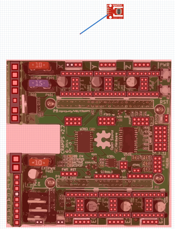
However I created SVG with imported image, and then I find out at some point my image is of board (that was imported in inkscape as bitmap) is not shown anymore.
So question - can SVG contain bitmap or not? Is this something that is “normal approach” for creating part?
While I’ve not done it, bitmaps (for breadboard view anyway) can be imported. If it is being truncated I’d probably check that it is contained within your viewbox in Inkscape as I believe things outside the viewbox will be truncated. Below are pointers to a couple of the latest parts creation tutorials (there are more on the Fritzing main page):
Import into Inkscape, Path/Trace Bitmap, delete bitmap, and then just work with the vectors.
OK tried with Path/trace but this didn’t produced nice output.
I had more luck with http://vectormagic.com service which produced nice tracet svg.
With vectormagic produced svg - I don’t loose part anymore (like that was case when using bitmap image inside svg).
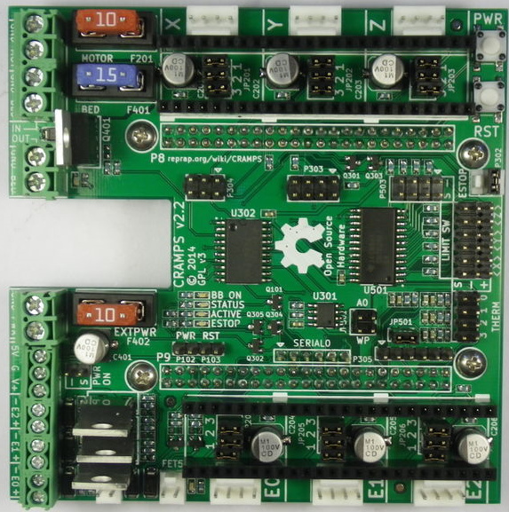
Since I want to make fritz part of:
Beaglebone Cramps Hat
I find specifying pins very troublesome (I have 230 pins) - is there any way to import from spreadsheet or modify connectors in simple editor?
That is one for the coding experts, but probably not.
Even if you imported the code you would still have to give each individual location coordinates, making each one different.
It would probably be easier to make a node, duplicate it, and move it to the pin.
Hints
Scale part until pins are at 0.100" spacing.
Make sure pin nodes are to the top.
Number pins in order.
Add a 0 stroke terminal numbered in order for auto assign in Fritzing.
Watch the video.
Take apart Steel’s last part and reverse engineer it to see how it’s done.
What you want to do is similar to this one that someone else wanted. The explaination of how I added the missing pins using a text editor for the fpz and Inkscape for the svg may also help you. It is going to be tedious no matter I expect but perhaps easier than parts editor if that is what you are currently using. It could be scripted (with effort ![]() ) but as Old_Grey pointed out the coords for the connections are going to be exciting to produce.
) but as Old_Grey pointed out the coords for the connections are going to be exciting to produce.
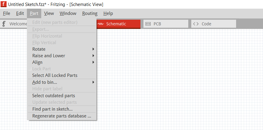
Ok i did it manualy for board, but now I want to have copy of board in schematics (in part editor).
Is there a shortcut to do this? Can I just import svg from board into schematics?
Doing it manually would take me an hour.
Oh yes it is possible to import boart into schematics! Great!
What it means if my custom part is red in BOARD view?
It seems I cannot use it:
I completed board part of view (in part editor) - doesn’t this means I should be able to use it in Board view of fritzing? However it is true - my part being so complex still doesn’t have pcb view…
Why couldn’t I use it on board view? Why red color? What it means - where are errors or messages so I can know what is wrong?
The red indicates that Fritzing is unhappy with your pin layout probably in pcb view which you indicate you don’t have. I think there is a way to supress pcb view but I don’t know it (I expect someone else will chip in  ). It may be easiest just to create a pcb view with pads for all the connectors (preferably mechanically accurate, but as long as the pads are there it doesn’t have to be). I think that parts editor under connectors should tell you which pins it is unhappy about (I rarely use parts editor so can’t be more specific).
It’s telling you the pins aren’t assigned.
You can assign the pins in FZ Parts Editor, or I think you can add a zero stroke node on your connector node to auto assign.
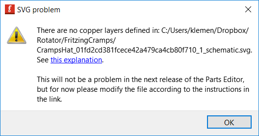
I tried to import same svg from boart to pcb - but it says it cannot find copper layer.
I tried to open svg in inkscape - grouped object and add id=“copper0” in properties of group, and reimport in parteditor pcb - but sabe - it cannot find copper… tryy to search inforum about copper error cut couldn’t find anything…
Any idea how to priperly reimport in pcb so big part? I do not want to do it manualy again.
I done same thing in schematics and imported it succesfully.
This is error:
That is what is looks like… at least one of your pins in the .fzp are not associated with a pin in the breadoard.svg. It only take one… could be misslabeled or just misspelled.
Try this, open the part up in the parts editor, in breaboard view, then on the right under connectors, pan down though the list to see which ones don’t have a check next to it. You can connect them there or go to the .svg or .fzp and fix the problem.
It tells you about copper in the video that was posted above. Have you watched it?
If you can’t fix it then just send me the .fzpz and I will fix it for you…
You are all correct. When I save I have:
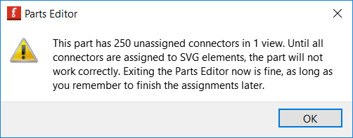
But in board and schematics view all check are there in near connector names - so all populated.
So I thought I could use part in board and schematics at least let alone pcb.
fritzing.fzz (421.6 KB)
@Old_Grey: Where is the link to video?
I tried searching forum and seems other have same problem:
in
http://fritzing.org/forum/thread/1334/?page=last#post6414
@joneff author says:
I’ve been having trouble with the “no copper layer defined” -error
Breadboard and schema SVG import from Inkscape work perfectly. But PCB SVG import fails with “there is no copper layer definec” … although there is.
I got it to work, and here are my workarounds:
- if the SVG is in mm, the PCB image will be off-scale. Apparently the import doesn’t check for units. This problem only for the PCB svg.
- the copper layer has to be described in the .svg with two nested tags like this
…
I do not know why a single tag with id=copper doesnt suffice, but this is how I got it to import.
Third post down on this actual topic.
Here it is again.