Type
I did not read this
Breakout board, sub assembly, plug in module (A)
Antenna (AE)
Battery (BT)
Capacitor (C)
Diode (D)
Display (DS)
Fuse (F)
Hardware , mounting screws, etc. (H)
Jack, fixed part of a connector pair, header (J)
Relay (K)
Inductor, Coil, Ferrite bead (L)
Loudspeaker, Buzzer (LS)
Motor (M)
Microphone (MK)
Plug, moveable part of a connector pair (P)
Transistor (Q)
Resistor (R)
Thermistor (RT)
Varistor (RV)
Switch (S)
Transformer (T)
Integrated Circuit (IC)
Crystal, Oscillator (Y)
Zender diode (Z)
Other (please specifiy)
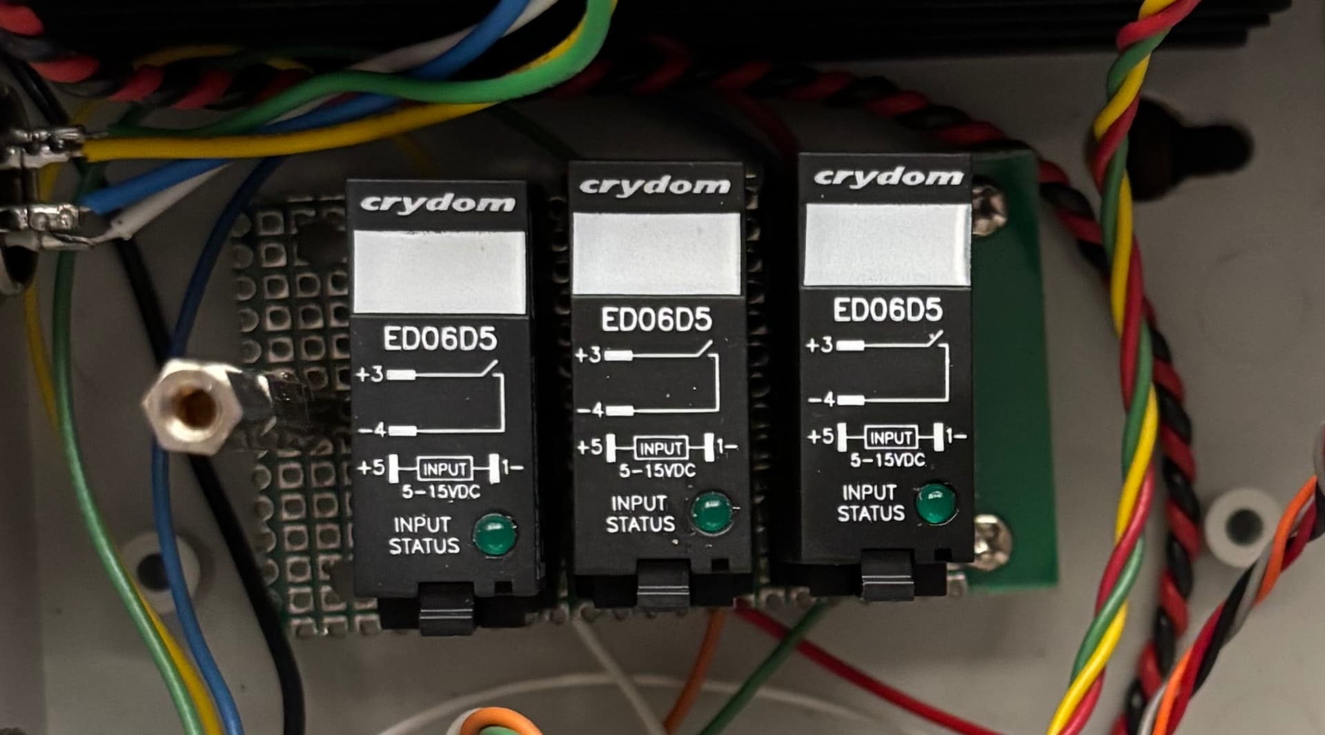
I’m struggling with creating a new part from scratch. I also sent in a request to have this part made through the form on the website but haven’t gotten a response. Can anyone help me with this? Thanks in advance.
This part may do what you want. Their data sheet lacks pin numbers in the socket and lacks what view (from the top or the bottom) a particular diagram is so the part is entirely a guess and may be wrong. Before ordering boards print the pcb footprint out at 1:1 scale and compare it to a real part and verify the pins are in the correct place.
edit:
Replace the part to correct the pin spacing slightly from the new information below. Note if you have already downloaded the original part you will need to delete the part in the mine parts bin by right clicking on it then selecting delete part. After that to actually delete the part you need to shut down Fritzing and answer yes to save parts and yes to save parts bin (you can answer no to save the sketch though.) On restarting Fritzing it should let you load the corrected part.
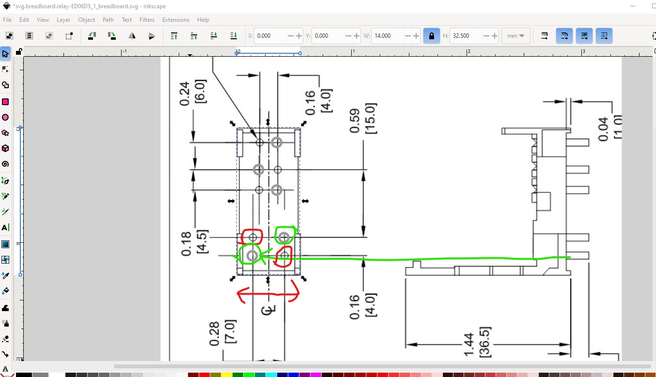
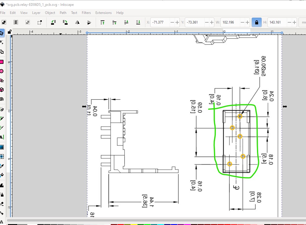
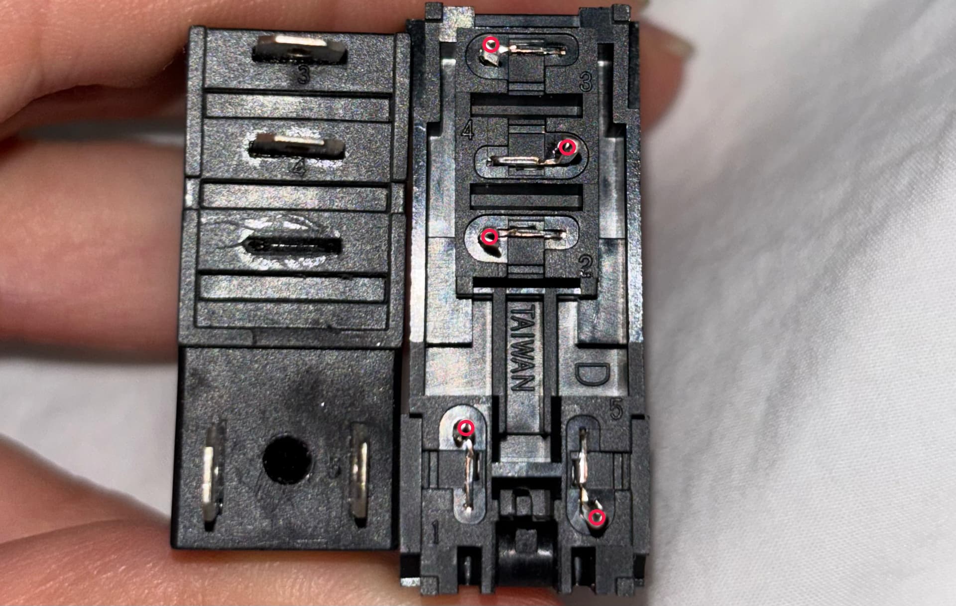
OK, the new information gave me a better image of the socket, there are still no pin numbers listed but I could at least see that in deed the views are non standard. This is the socket from one of the new data sheets which indicates the image on the left is viewed from the bottom (which is what I had assumed) and thus needs to be flipped in horizontal to be viewed from the top which Fritzing is expecting. As well I managed to screw up the spacing between the pins a bit which is now corrected.
Now when I import the above image and scale it correctly the pins line up correctly with the image (the image here is flipped in horizontal so it is the view from the top of the socket.)
I have replaced the part in the post above with the new one. As the edit comment there says, if you have downloaded the part already you will need to delete it and then shutdown Fritzing (to really delete it) before it will let you load the new part. The socket still has no pin numbers listed (only the relay itself has the pin numbers) so checking that the socket pins go to the expected pin on the relay it self would be a good bet. I think it is right as it stands but it may not be.