Type
I did not read this
X Breakout board, sub assembly, plug in module (A)
Antenna (AE)
Battery (BT)
Capacitor (C)
Diode (D)
Display (DS)
Fuse (F)
Hardware , mounting screws, etc. (H)
Jack, fixed part of a connector pair, header (J)
Relay (K)
Inductor, Coil, Ferrite bead (L)
Loudspeaker, Buzzer (LS)
Motor (M)
Microphone (MK)
Plug, moveable part of a connector pair (P)
Transistor (Q)
Resistor (R)
Thermistor (RT)
Varistor (RV)
Switch (S)
Transformer (T)
Integrated Circuit (IC)
Crystal, Oscillator (Y)
Zender diode (Z)
Other (please specifiy)
Footprint
E.g. SOT23-5 , TO-220.
This usually does not apply to breakout boards.
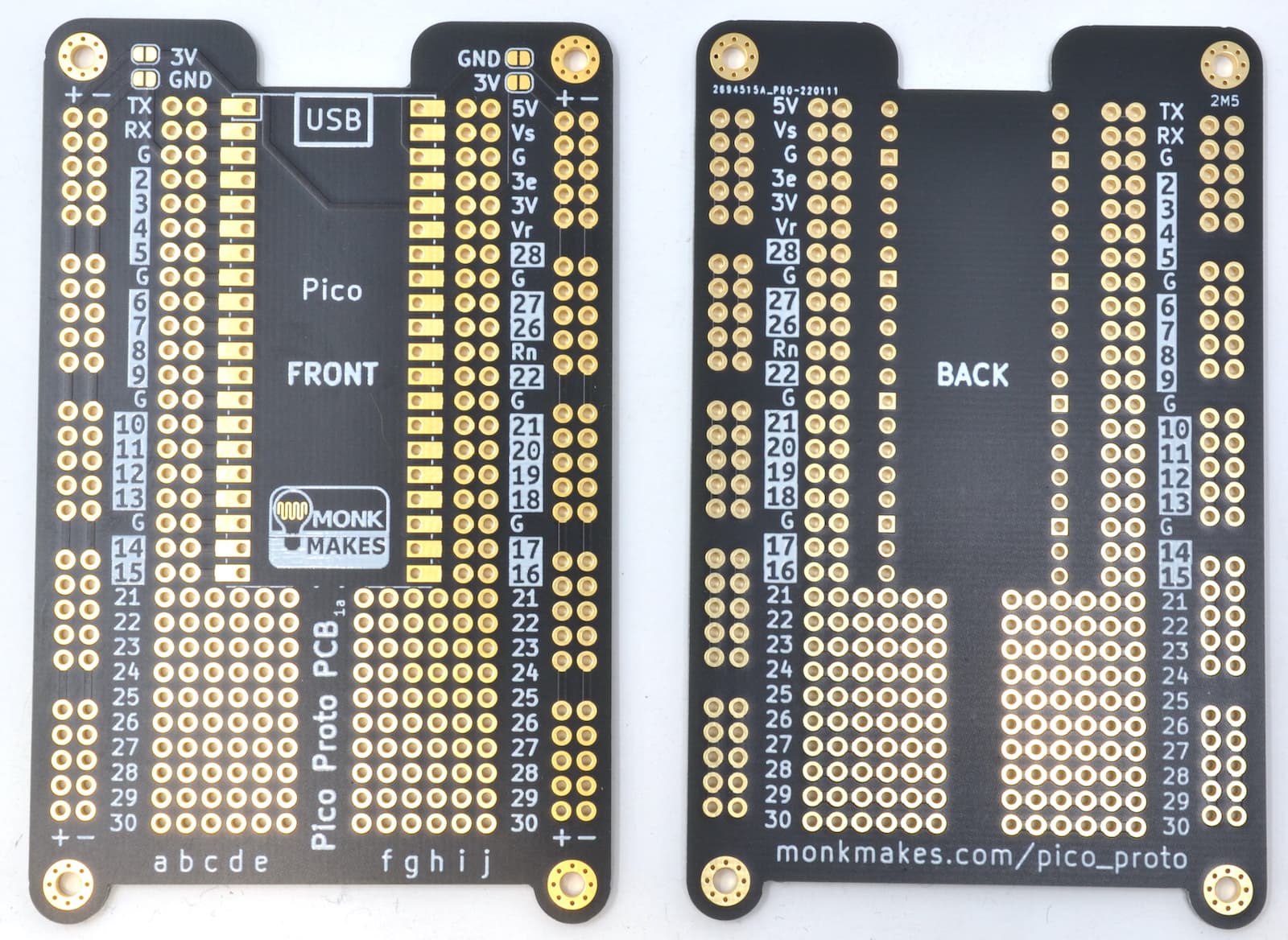
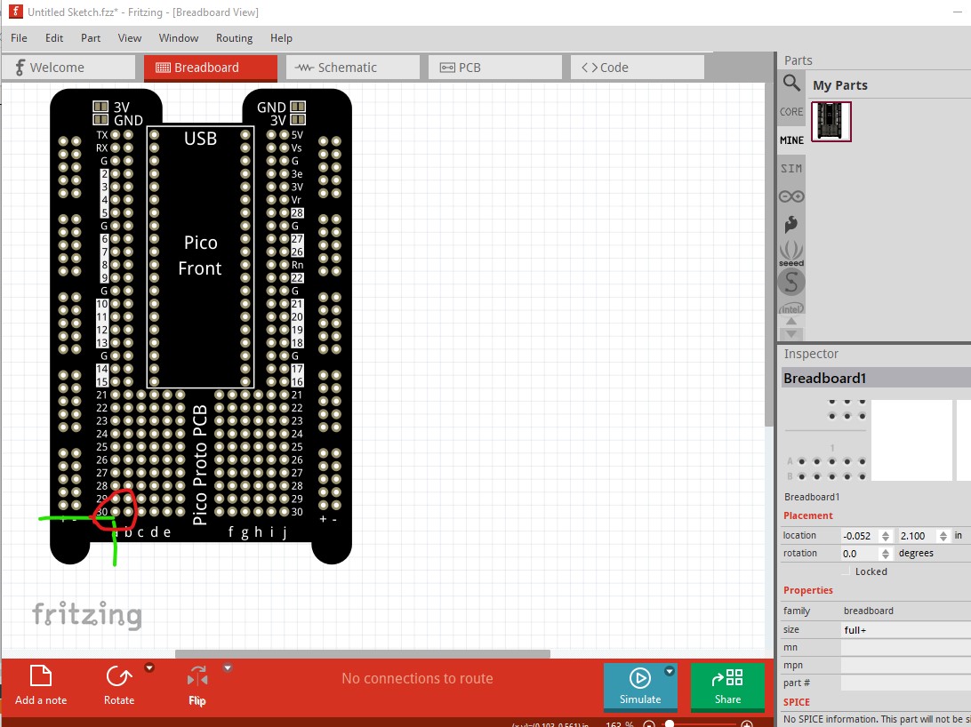
Insufficient information available to make a part. There is no indication of which pins are bussed. I would assume (without proof) that the power busses are a bus. It is unclear what the solder pins for the power busses connect to when soldered. It is unclear if the pico pins are bussed to the pins on the pico (although that seems likely) and their documentation doesn’t provide any information. It is also a very complex part to make even if there was sufficient information, but the lack of information is fatal.
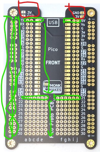
The 3v(+), GND(-), and pico pins are bussed. The lower strips (21-30) are bussed on each side. So rows 21-30 are bussed for the 6 pins on the left side and the 6 pins on the right separately. kind of like a breadboard.
Note that default grid size may not align pico and other components properly to the board pins, as fritzing will choose the reference connector to align with at random
Fritzing uses the first connector as reference for grid alignment.
This is a problem with parts like this, since a 0.1 grid size will either match the power lines at the side, or the board connectors in the center, and these are set 0.05 inch apart.
Fritzing should use one or the other, but always the same, not at random. When creating the part, you can decide by putting the reference connector first.
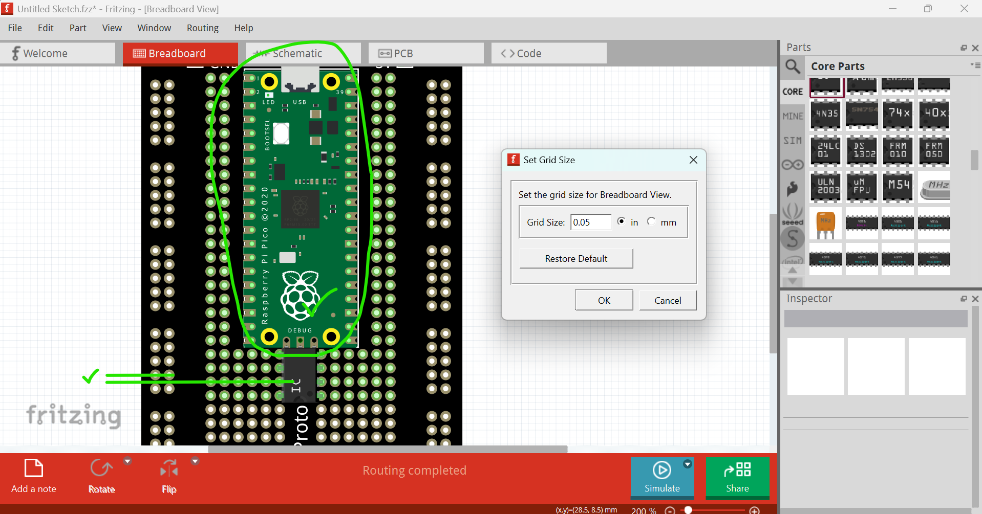
Using a half size grid (50mil) is a good workaroud for the issue.
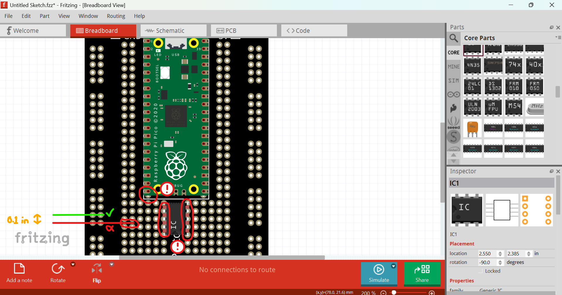
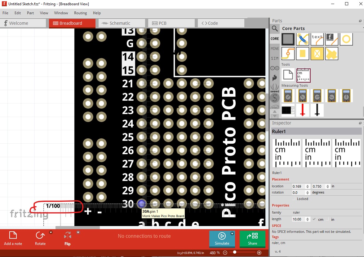
From experience that is not true. If you load a part with off grid pins multiple times Fritzing will sometimes change the reference pin and select one of the offset pins making all the pins intended to be on the grid offset by the space of the non aligned pin it chose as a reference. This part provides a good demonstration (I believe there is an issue open on correcting this on github as it is very annoying!) Loaded the part and dragged it in to breadboard. Pin 0 is not aligned to the grid the power strips are:
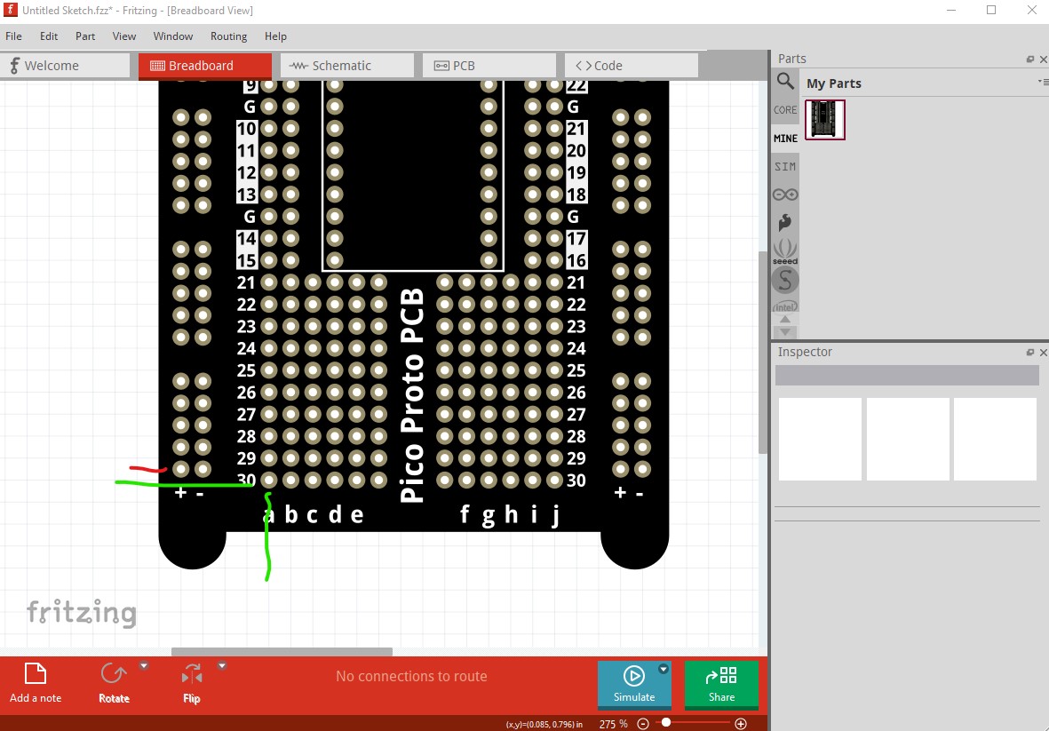
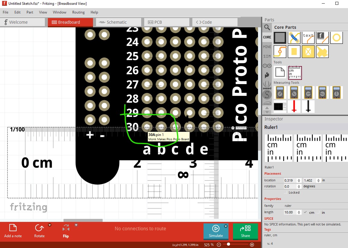
Now delete the part and shutdown Fritzing (so it will need to be reloaded, because I think this happens at load!.) Luckily for me this one aligned correctly (you sometimes need to go through this cycle a number of times to get a misaligned part.)